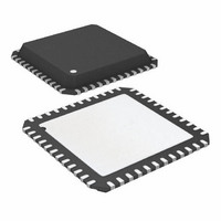
AT91SAM7S16-MU Atmel, AT91SAM7S16-MU Datasheet - Page 451

AT91SAM7S16-MU
Manufacturer Part Number
AT91SAM7S16-MU
Description
MCU ARM 16K HI SPD FLASH 48-QFN
Manufacturer
Atmel
Series
AT91SAMr
Specifications of AT91SAM7S16-MU
Core Processor
ARM7
Core Size
16/32-Bit
Speed
55MHz
Connectivity
I²C, SPI, SSC, UART/USART
Peripherals
Brown-out Detect/Reset, DMA, POR, PWM, WDT
Number Of I /o
21
Program Memory Size
16KB (16K x 8)
Program Memory Type
FLASH
Ram Size
4K x 8
Voltage - Supply (vcc/vdd)
1.65 V ~ 1.95 V
Data Converters
A/D 8x10b
Oscillator Type
Internal
Operating Temperature
-40°C ~ 85°C
Package / Case
48-QFN Exposed Pad
For Use With
AT91SAM-ICE - EMULATOR FOR AT91 ARM7/ARM9AT91SAM7S-EK - KIT EVAL FOR ARM AT91SAM7S
Lead Free Status / RoHS Status
Lead free / RoHS Compliant
Eeprom Size
-
- Current page: 451 of 779
- Download datasheet (11Mb)
33.5.10
33.5.11
6175K–ATARM–30-Aug-10
Waveform Operating Mode
Waveform Selection
Waveform operating mode is entered by setting the WAVE parameter in TC_CMR (Channel
Mode Register).
In Waveform Operating Mode the TC channel generates 1 or 2 PWM signals with the same fre-
quency and independently programmable duty cycles, or generates different types of one-shot
or repetitive pulses.
In this mode, TIOA is configured as an output and TIOB is defined as an output if it is not used
as an external event (EEVT parameter in TC_CMR).
Figure 33-6
ing Mode.
Depending on the WAVSEL parameter in TC_CMR (Channel Mode Register), the behavior of
TC_CV varies.
With any selection, RA, RB and RC can all be used as compare registers.
RA Compare is used to control the TIOA output, RB Compare is used to control the TIOB output
(if correctly configured) and RC Compare is used to control TIOA and/or TIOB outputs.
shows the configuration of the TC channel when programmed in Waveform Operat-
AT91SAM7S Series Preliminary
451
Related parts for AT91SAM7S16-MU
Image
Part Number
Description
Manufacturer
Datasheet
Request
R

Part Number:
Description:
KIT EVAL FOR ARM AT91SAM7S
Manufacturer:
Atmel
Datasheet:

Part Number:
Description:
MCU, MPU & DSP Development Tools KICKSTART KIT ATMEL AT91SAM7S
Manufacturer:
IAR Systems

Part Number:
Description:
DEV KIT FOR AVR/AVR32
Manufacturer:
Atmel
Datasheet:

Part Number:
Description:
INTERVAL AND WIPE/WASH WIPER CONTROL IC WITH DELAY
Manufacturer:
ATMEL Corporation
Datasheet:

Part Number:
Description:
Low-Voltage Voice-Switched IC for Hands-Free Operation
Manufacturer:
ATMEL Corporation
Datasheet:

Part Number:
Description:
MONOLITHIC INTEGRATED FEATUREPHONE CIRCUIT
Manufacturer:
ATMEL Corporation
Datasheet:

Part Number:
Description:
AM-FM Receiver IC U4255BM-M
Manufacturer:
ATMEL Corporation
Datasheet:

Part Number:
Description:
Monolithic Integrated Feature Phone Circuit
Manufacturer:
ATMEL Corporation
Datasheet:

Part Number:
Description:
Multistandard Video-IF and Quasi Parallel Sound Processing
Manufacturer:
ATMEL Corporation
Datasheet:

Part Number:
Description:
High-performance EE PLD
Manufacturer:
ATMEL Corporation
Datasheet:

Part Number:
Description:
8-bit Flash Microcontroller
Manufacturer:
ATMEL Corporation
Datasheet:

Part Number:
Description:
2-Wire Serial EEPROM
Manufacturer:
ATMEL Corporation
Datasheet:


