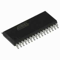
AT90PWM3B-16SU Atmel, AT90PWM3B-16SU Datasheet - Page 349

AT90PWM3B-16SU
Manufacturer Part Number
AT90PWM3B-16SU
Description
IC MCU AVR RISC 8K FLASH 32-SOIC
Manufacturer
Atmel
Series
AVR® 90PWM Lightingr
Specifications of AT90PWM3B-16SU
Core Processor
AVR
Core Size
8-Bit
Speed
16MHz
Connectivity
SPI, UART/USART
Peripherals
Brown-out Detect/Reset, POR, PWM, WDT
Number Of I /o
27
Program Memory Size
8KB (8K x 8)
Program Memory Type
FLASH
Eeprom Size
512 x 8
Ram Size
512 x 8
Voltage - Supply (vcc/vdd)
2.7 V ~ 5.5 V
Data Converters
A/D 11x10b; D/A 1x10b
Oscillator Type
Internal
Operating Temperature
-40°C ~ 105°C
Package / Case
32-SOIC (7.5mm Width)
Processor Series
AT90PWMx
Core
AVR8
Data Bus Width
8 bit
Data Ram Size
512 B
Interface Type
SPI/USART
Maximum Clock Frequency
16 MHz
Number Of Programmable I/os
27
Number Of Timers
2
Operating Supply Voltage
2.7 V to 5.5 V
Maximum Operating Temperature
+ 105 C
Mounting Style
SMD/SMT
3rd Party Development Tools
EWAVR, EWAVR-BL
Development Tools By Supplier
ATAVRDRAGON, ATSTK500, ATSTK600, ATAVRISP2, ATAVRONEKIT, ATAVRFBKIT, ATAVRISP2
Minimum Operating Temperature
- 40 C
On-chip Adc
11-ch x 10-bit
On-chip Dac
1-chx10-bit
Controller Family/series
AVR PWM
Eeprom Memory Size
512Byte
Ram Memory Size
512Byte
Cpu Speed
16MHz
Rohs Compliant
Yes
For Use With
ATSTK600-SOIC - STK600 SOCKET/ADAPTER FOR SOIC770-1007 - ISP 4PORT ATMEL AVR MCU SPI/JTAGATAVRMC200 - KIT EVAL FOR AT90PWM3 ASYNCATAVRFBKIT - KIT DEMO BALLAST FOR AT90PWM2ATAVRISP2 - PROGRAMMER AVR IN SYSTEMATSTK520 - ADAPTER KIT FOR 90PWM
Lead Free Status / RoHS Status
Lead free / RoHS Compliant
Available stocks
Company
Part Number
Manufacturer
Quantity
Price
Company:
Part Number:
AT90PWM3B-16SU
Manufacturer:
Atmel
Quantity:
4 000
Part Number:
AT90PWM3B-16SU
Manufacturer:
MICROCHIP/微芯
Quantity:
20 000
- Current page: 349 of 361
- Download datasheet (7Mb)
4317J–AVR–08/10
5. PSC: Output Polarity in Centered Mode
6. PSC : POACnA/B Output Activity
7. VREF
8. DALI
9. DAC: Register Update
10. DAC : Output spikes
11. DAC driver: Output Voltage linearity
12. ADC : Conversion accuracy
13. Analog comparator: Offset value
14. Analog comparator: Output signal
In centered mode, PSCOUTn1 outputs are not inverted, so they are active at the same time
as PSCOUTn0.
Workaround:
Use an external inverter (or a driver with inverting output) to drive the load on
PSCOUTn1.
These register bits are not implemented in rev A.
Workaround:
Do not use this feature.
Remark: To have Internal Vref on AREF pin select an internal analog feature such as DAC
or ADC.
Some stand by power consuption may be observed if Vref equals AVcc
Some troubles on Dali extension when edges are not symmetric.
Workaround:
Use an optocoupler providing symmetric edges on Rx and Tx DALI lines (only recom-
manded for software validation purpose).
Registers DACL & DACH are not written when the DAC is not enabled.
Workaround:
Enable DAC with DAEN before writing in DACL & DACH. To prevent an unwanted zero out-
put on DAC pin, enable DAC output, with DAOE afterwards.
During transition between two codes, a spike may appears
Work around:
Filter spike or wait for steady state
No spike appears if the 4 last signifiant bits remain zero.
The voltage linearity of the DAC driver is limited when the DAC output goes above Vcc - 1V.
Work around:
Do not use AVcc as Vref ; internal Vref gives good results
The conversion accuracy degrades when the ADC clock is 1 & 2 MHz.
Work around:
When a 10 bit conversion accuracy is required, use an ADC clock of 500 kHz or below.
The offset value increases when the common mode voltage is above Vcc - 1.5V.
Work around:
Limit common mode voltage
AT90PWM2/3/2B/3B
349
Related parts for AT90PWM3B-16SU
Image
Part Number
Description
Manufacturer
Datasheet
Request
R

Part Number:
Description:
Manufacturer:
Atmel Corporation
Datasheet:

Part Number:
Description:
IC MCU AVR RISC 8K FLASH 32-QFN
Manufacturer:
Atmel
Datasheet:

Part Number:
Description:
MCU AVR 8K FLASH 16MHA 32SOIC
Manufacturer:
Atmel
Datasheet:

Part Number:
Description:
IC AVR MCU FLASH 8K 32QFN
Manufacturer:
Atmel
Datasheet:

Part Number:
Description:
IC AVR MCU FLASH 8K 32SOIC
Manufacturer:
Atmel
Datasheet:

Part Number:
Description:
MCU AVR 8K FLASH 16MHZ 32-QFN
Manufacturer:
Atmel
Datasheet:

Part Number:
Description:
DEV KIT FOR AVR/AVR32
Manufacturer:
Atmel
Datasheet:

Part Number:
Description:
INTERVAL AND WIPE/WASH WIPER CONTROL IC WITH DELAY
Manufacturer:
ATMEL Corporation
Datasheet:

Part Number:
Description:
Low-Voltage Voice-Switched IC for Hands-Free Operation
Manufacturer:
ATMEL Corporation
Datasheet:

Part Number:
Description:
MONOLITHIC INTEGRATED FEATUREPHONE CIRCUIT
Manufacturer:
ATMEL Corporation
Datasheet:

Part Number:
Description:
AM-FM Receiver IC U4255BM-M
Manufacturer:
ATMEL Corporation
Datasheet:

Part Number:
Description:
Monolithic Integrated Feature Phone Circuit
Manufacturer:
ATMEL Corporation
Datasheet:

Part Number:
Description:
Multistandard Video-IF and Quasi Parallel Sound Processing
Manufacturer:
ATMEL Corporation
Datasheet:


