TOOLSTICK542PP Silicon Laboratories Inc, TOOLSTICK542PP Datasheet - Page 261
TOOLSTICK542PP
Manufacturer Part Number
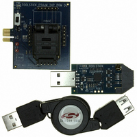
TOOLSTICK542PP
Description
PLATFORM PROG TOOLSTICK F542
Manufacturer
Silicon Laboratories Inc
Series
ToolStickr
Type
Microcontroller Programmerr
Specifications of TOOLSTICK542PP
Contents
2 Boards and USB Connecting Cable
Processor To Be Evaluated
C8051F542
Interface Type
USB
Operating Supply Voltage
2.7 V to 3.6 V
Lead Free Status / RoHS Status
Lead free / RoHS Compliant
For Use With/related Products
C8051F542
Lead Free Status / Rohs Status
Lead free / RoHS Compliant
Other names
336-1718


Note that the 8-bit offset held in PCA0CPH5 is compared to the upper byte of the 16-bit PCA counter. This
offset value is the number of PCA0L overflows before a reset. Up to 256 PCA clocks may pass before the
first PCA0L overflow occurs, depending on the value of the PCA0L when the update is performed. The
total offset is then given (in PCA clocks) by Equation 24.5, where PCA0L is the value of the PCA0L register
at the time of the update.
The WDT reset is generated when PCA0L overflows while there is a match between PCA0CPH5 and
PCA0H. Software may force a WDT reset by writing a 1 to the CCF5 flag (PCA0CN.5) while the WDT is
enabled.
24.4.2. Watchdog Timer Usage
To configure the WDT, perform the following tasks:
The PCA clock source and Idle mode select cannot be changed while the WDT is enabled. The watchdog
timer is enabled by setting the WDTE or WDLCK bits in the PCA0MD register. When WDLCK is set, the
WDT cannot be disabled until the next system reset. If WDLCK is not set, the WDT is disabled by clearing
the WDTE bit.
The WDT is enabled following any reset. The PCA0 counter clock defaults to the system clock divided by
12, PCA0L defaults to 0x00, and PCA0CPL5 defaults to 0x00. Using Equation 24.5, this results in a WDT
timeout interval of 256 PCA clock cycles, or 3072 system clock cycles. Table 24.3 lists some example time-
out intervals for typical system clocks.
Disable the WDT by writing a 0 to the WDTE bit.
Select the desired PCA clock source (with the CPS[2:0] bits).
Load PCA0CPL5 with the desired WDT update offset value.
Configure the PCA Idle mode (set CIDL if the WDT should be suspended while the CPU is in Idle
mode).
Enable the WDT by setting the WDTE bit to 1.
Reset the WDT timer by writing to PCA0CPH5.
PCA0CPL5
C
D
L
I
W
D
T
E
PCA0MD
W
D
C
K
L
PCA0CPH2
C
P
S
2
Figure 24.11. PCA Module 2 with Watchdog Timer Enabled
Write to
C
P
S
1
C
P
S
0
Equation 24.5. Watchdog Timer Offset in PCA Clocks
E
C
F
Offset
8-bit Adder
=
Enable
Adder
256
x
Enable
PCA0CPL5
Rev. 1.1
PCA0CPH5
Comparator
PCA0H
8-bit
+
256 PCA0L
–
Match
PCA0L Overflow
C8051F54x
Reset
261
Related parts for TOOLSTICK542PP
Image
Part Number
Description
Manufacturer
Datasheet
Request
R

Part Number:
Description:
KIT TOOL EVAL SYS IN A USB STICK
Manufacturer:
Silicon Laboratories Inc
Datasheet:

Part Number:
Description:
TOOLSTICK DEBUG ADAPTER
Manufacturer:
Silicon Laboratories Inc
Datasheet:

Part Number:
Description:
TOOLSTICK BASE ADAPTER
Manufacturer:
Silicon Laboratories Inc
Datasheet:

Part Number:
Description:
TOOLSTICK DAUGHTER CARD
Manufacturer:
Silicon Laboratories Inc
Datasheet:

Part Number:
Description:
TOOLSTICK DAUGHTER CARD
Manufacturer:
Silicon Laboratories Inc
Datasheet:

Part Number:
Description:
TOOLSTICK DAUGHTER CARD
Manufacturer:
Silicon Laboratories Inc
Datasheet:

Part Number:
Description:
TOOLSTICK DAUGHTER CARD
Manufacturer:
Silicon Laboratories Inc
Datasheet:

Part Number:
Description:
KIT STARTER TOOLSTICK
Manufacturer:
Silicon Laboratories Inc
Datasheet:

Part Number:
Description:
KIT UNIVERSITY TOOLSTICK STARTER
Manufacturer:
Silicon Laboratories Inc
Datasheet:

Part Number:
Description:
DAUGHTER CARD TOOLSTICK F330
Manufacturer:
Silicon Laboratories Inc
Datasheet:

Part Number:
Description:
CARD DAUGHTER UNIVRSTY TOOLSTICK
Manufacturer:
Silicon Laboratories Inc
Datasheet:

Part Number:
Description:
DAUGHTER CARD TOOLSTICK F582
Manufacturer:
Silicon Laboratories Inc
Datasheet:

Part Number:
Description:
DAUGHTER CARD TOOLSTICK F500
Manufacturer:
Silicon Laboratories Inc
Datasheet:

Part Number:
Description:
DAUGHTER CARD TOOLSTICK F540
Manufacturer:
Silicon Laboratories Inc
Datasheet:

Part Number:
Description:
DAUGHTER CARD TOOLSTICK F560
Manufacturer:
Silicon Laboratories Inc
Datasheet: