TOOLSTICK542PP Silicon Laboratories Inc, TOOLSTICK542PP Datasheet - Page 133
TOOLSTICK542PP
Manufacturer Part Number
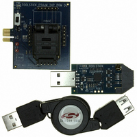
TOOLSTICK542PP
Description
PLATFORM PROG TOOLSTICK F542
Manufacturer
Silicon Laboratories Inc
Series
ToolStickr
Type
Microcontroller Programmerr
Specifications of TOOLSTICK542PP
Contents
2 Boards and USB Connecting Cable
Processor To Be Evaluated
C8051F542
Interface Type
USB
Operating Supply Voltage
2.7 V to 3.6 V
Lead Free Status / RoHS Status
Lead free / RoHS Compliant
For Use With/related Products
C8051F542
Lead Free Status / Rohs Status
Lead free / RoHS Compliant
Other names
336-1718


16.5. Comparator0 Reset
Comparator0 can be configured as a reset source by writing a 1 to the C0RSEF flag (RSTSRC.5).
Comparator0 should be enabled and allowed to settle prior to writing to C0RSEF to prevent any turn-on
chatter on the output from generating an unwanted reset. The Comparator0 reset is active-low: if the non-
inverting input voltage (on CP0+) is less than the inverting input voltage (on CP0–), the device is put into
the reset state. After a Comparator0 reset, the C0RSEF flag (RSTSRC.5) will read 1 signifying
Comparator0 as the reset source; otherwise, this bit reads 0. The state of the RST pin is unaffected by this
reset.
16.6. PCA Watchdog Timer Reset
The programmable Watchdog Timer (WDT) function of the Programmable Counter Array (PCA) can be
used to prevent software from running out of control during a system malfunction. The PCA WDT function
can be enabled or disabled by software as described in Section “24.4. Watchdog Timer Mode” on
page 260; the WDT is enabled and clocked by SYSCLK/12 following any reset. If a system malfunction
prevents user software from updating the WDT, a reset is generated and the WDTRSF bit (RSTSRC.5) is
set to 1. The state of the RST pin is unaffected by this reset.
16.7. Flash Error Reset
If a Flash read/write/erase or program read targets an illegal address, a system reset is generated. This
may occur due to any of the following:
The FERROR bit (RSTSRC.6) is set following a Flash error reset. The state of the RST pin is unaffected by
this reset.
16.8. Software Reset
Software may force a reset by writing a 1 to the SWRSF bit (RSTSRC.4). The SWRSF bit will read 1 fol-
lowing a software forced reset. The state of the RST pin is unaffected by this reset.
A Flash write or erase is attempted above user code space. This occurs when PSWE is set to 1 and a
MOVX write operation targets an address in or above the reserved space.
A Flash read is attempted above user code space. This occurs when a MOVC operation targets an
address in or above the reserved space.
A Program read is attempted above user code space. This occurs when user code attempts to branch
to an address in or above the reserved space.
A Flash read, write or erase attempt is restricted due to a Flash security setting (see Section
“14.3. Security Options” on page 119).
A Flash read, write, or erase is attempted when the VDD Monitor is not enabled to the high threshold
and set as a reset source.
Rev. 1.1
C8051F54x
133
Related parts for TOOLSTICK542PP
Image
Part Number
Description
Manufacturer
Datasheet
Request
R

Part Number:
Description:
KIT TOOL EVAL SYS IN A USB STICK
Manufacturer:
Silicon Laboratories Inc
Datasheet:

Part Number:
Description:
TOOLSTICK DEBUG ADAPTER
Manufacturer:
Silicon Laboratories Inc
Datasheet:

Part Number:
Description:
TOOLSTICK BASE ADAPTER
Manufacturer:
Silicon Laboratories Inc
Datasheet:

Part Number:
Description:
TOOLSTICK DAUGHTER CARD
Manufacturer:
Silicon Laboratories Inc
Datasheet:

Part Number:
Description:
TOOLSTICK DAUGHTER CARD
Manufacturer:
Silicon Laboratories Inc
Datasheet:

Part Number:
Description:
TOOLSTICK DAUGHTER CARD
Manufacturer:
Silicon Laboratories Inc
Datasheet:

Part Number:
Description:
TOOLSTICK DAUGHTER CARD
Manufacturer:
Silicon Laboratories Inc
Datasheet:

Part Number:
Description:
KIT STARTER TOOLSTICK
Manufacturer:
Silicon Laboratories Inc
Datasheet:

Part Number:
Description:
KIT UNIVERSITY TOOLSTICK STARTER
Manufacturer:
Silicon Laboratories Inc
Datasheet:

Part Number:
Description:
DAUGHTER CARD TOOLSTICK F330
Manufacturer:
Silicon Laboratories Inc
Datasheet:

Part Number:
Description:
CARD DAUGHTER UNIVRSTY TOOLSTICK
Manufacturer:
Silicon Laboratories Inc
Datasheet:

Part Number:
Description:
DAUGHTER CARD TOOLSTICK F582
Manufacturer:
Silicon Laboratories Inc
Datasheet:

Part Number:
Description:
DAUGHTER CARD TOOLSTICK F500
Manufacturer:
Silicon Laboratories Inc
Datasheet:

Part Number:
Description:
DAUGHTER CARD TOOLSTICK F540
Manufacturer:
Silicon Laboratories Inc
Datasheet:

Part Number:
Description:
DAUGHTER CARD TOOLSTICK F560
Manufacturer:
Silicon Laboratories Inc
Datasheet: