MPC8349E-MDS-PBE Freescale Semiconductor, MPC8349E-MDS-PBE Datasheet - Page 5
MPC8349E-MDS-PBE
Manufacturer Part Number
MPC8349E-MDS-PBE
Description
KIT MODULAR DEV SYSTEM MPC8349E
Manufacturer
Freescale Semiconductor
Datasheet
1.MPC8349EA-MDS-PB.pdf
(8 pages)
Specifications of MPC8349E-MDS-PBE
Lead Free Status / RoHS Status
Lead free / RoHS Compliant


Switches: SW7 Configuration Set 4
Switches: SW2 Software Option
Switches: SW5 Power Switch
Jumper: JP1
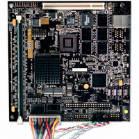
MPC8349E MDS Processor Board HW Getting Started Guide
JP1
1
Internal Clock
1: CORPLL0
2: CORPLL1
3: CORPLL2
4: CORPLL3
5: CORPLL4
6: CORPLL5
7: CORPLL6
8: COREDIS
Source
PCB
JP1
External Clock
1 <-> 0
ON
1
Source
SW7.1-SW7.7: Core PLL setting
SW7.3-SW7.5: Core disable
SW2: Software option
SW5: Power switch
JP1
• Sets the ratio between the e300 core clock and the internal
• Factory setting: ‘00001000' for core_clk = 533 MHz.
• Recommended secondary setting: ‘00000110’ for core_clk =
• Factory setting: ‘0'; core enabled for boot operation.
• Software BCD rotary-switch SW2 positions (0-7) enable
• Switch status is seen in BCSR10 bits 2-4.
• Factory setting: ‘0”
• ON: power from an external 5V power supply via the P11
• Combined mode: power from +5V on PIB power supply
• Board used as a PCI add-in card: PC internal power supply
• Selects the source for CLOCKIN signal.
• If a jumper is located between JP1 pins 1-2 (factory setting)
• The SHMOO mode clock source is I2C; manually programmed
• Close JP1 pins 2-3 to supply clock to a processor from an
csb_clk.
500 MHz.
program flow change.
power jack for standalone mode.
through riser connectors (regardless of SW5 position).
provides 5V via PCI edge connector (regardless of SW5
position).
then the processor is clocked from the on-board clock oscillator
U21 socket.
clock synthesizer residing on the PIB.
external generator via P5.
5
Related parts for MPC8349E-MDS-PBE
Image
Part Number
Description
Manufacturer
Datasheet
Request
R

Part Number:
Description:
BOARD REFERENCE FOR MPC8349
Manufacturer:
Freescale Semiconductor
Datasheet:

Part Number:
Description:
KIT REFERENCE PLATFORM MPC8349E
Manufacturer:
Freescale Semiconductor
Datasheet:

Part Number:
Description:
MCU, MPU & DSP Development Tools PROCESSR BD MPC8349E
Manufacturer:
Freescale Semiconductor
Part Number:
Description:
MCU, MPU & DSP Development Tools KIT FOR MPC8349E BDS
Manufacturer:
Freescale Semiconductor

Part Number:
Description:
Manufacturer:
Freescale Semiconductor, Inc
Datasheet:
Part Number:
Description:
Manufacturer:
Freescale Semiconductor, Inc
Datasheet:
Part Number:
Description:
Manufacturer:
Freescale Semiconductor, Inc
Datasheet:
Part Number:
Description:
Manufacturer:
Freescale Semiconductor, Inc
Datasheet:
Part Number:
Description:
Manufacturer:
Freescale Semiconductor, Inc
Datasheet:
Part Number:
Description:
Manufacturer:
Freescale Semiconductor, Inc
Datasheet:
Part Number:
Description:
Manufacturer:
Freescale Semiconductor, Inc
Datasheet:
Part Number:
Description:
Manufacturer:
Freescale Semiconductor, Inc
Datasheet:
Part Number:
Description:
Manufacturer:
Freescale Semiconductor, Inc
Datasheet:
Part Number:
Description:
Manufacturer:
Freescale Semiconductor, Inc
Datasheet:
Part Number:
Description:
Manufacturer:
Freescale Semiconductor, Inc
Datasheet: