MPC8349E-MDS-PBE Freescale Semiconductor, MPC8349E-MDS-PBE Datasheet - Page 3
MPC8349E-MDS-PBE
Manufacturer Part Number
MPC8349E-MDS-PBE
Description
KIT MODULAR DEV SYSTEM MPC8349E
Manufacturer
Freescale Semiconductor
Datasheet
1.MPC8349EA-MDS-PB.pdf
(8 pages)
Specifications of MPC8349E-MDS-PBE
Lead Free Status / RoHS Status
Lead free / RoHS Compliant


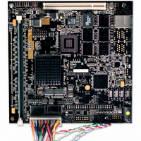
MPC8349E MDS Processor Board HW Getting Started Guide
Step 2: Connect plastic spacers.
Four sets of plastic spacers screw into
holes located at (approximately) the four
corners of the board.
The spacers raise and stabilize the board.
Step 3: Check switches and jumper.
The MPC8349E MDS processor board
has two rows of Dual-In-Line Package
(DIP) switches.
The default DIP-switch positions set-up
the MPC8349E MDS processor board
clock mode as shown in the table below:
1. From under the board, insert a male
2. Attach a female spacer onto the male
3. Repeat for the three remaining pairs
e300 Core Frequency
CCB
DDR
Local Bus
spacer into one of the board’s four
spacer holes.
spacer.
of spacers.
MPC8349E MDS Processor
Board Clock Mode
533 MHz
266 MHz
266 MHz
133 MHz
SW5
DIP-switches
set of plastic spacers
Socket for MPC8349E
SW7
SW6
JP1
SW4
SW3
SW2
SW5
Switches SW3, 4, 6, 7
3
Related parts for MPC8349E-MDS-PBE
Image
Part Number
Description
Manufacturer
Datasheet
Request
R

Part Number:
Description:
BOARD REFERENCE FOR MPC8349
Manufacturer:
Freescale Semiconductor
Datasheet:

Part Number:
Description:
KIT REFERENCE PLATFORM MPC8349E
Manufacturer:
Freescale Semiconductor
Datasheet:

Part Number:
Description:
MCU, MPU & DSP Development Tools PROCESSR BD MPC8349E
Manufacturer:
Freescale Semiconductor
Part Number:
Description:
MCU, MPU & DSP Development Tools KIT FOR MPC8349E BDS
Manufacturer:
Freescale Semiconductor

Part Number:
Description:
Manufacturer:
Freescale Semiconductor, Inc
Datasheet:
Part Number:
Description:
Manufacturer:
Freescale Semiconductor, Inc
Datasheet:
Part Number:
Description:
Manufacturer:
Freescale Semiconductor, Inc
Datasheet:
Part Number:
Description:
Manufacturer:
Freescale Semiconductor, Inc
Datasheet:
Part Number:
Description:
Manufacturer:
Freescale Semiconductor, Inc
Datasheet:
Part Number:
Description:
Manufacturer:
Freescale Semiconductor, Inc
Datasheet:
Part Number:
Description:
Manufacturer:
Freescale Semiconductor, Inc
Datasheet:
Part Number:
Description:
Manufacturer:
Freescale Semiconductor, Inc
Datasheet:
Part Number:
Description:
Manufacturer:
Freescale Semiconductor, Inc
Datasheet:
Part Number:
Description:
Manufacturer:
Freescale Semiconductor, Inc
Datasheet:
Part Number:
Description:
Manufacturer:
Freescale Semiconductor, Inc
Datasheet: