MPC8349E-MITX-GP Freescale Semiconductor, MPC8349E-MITX-GP Datasheet
MPC8349E-MITX-GP
Specifications of MPC8349E-MITX-GP


Related parts for MPC8349E-MITX-GP


MPC8349E-MITX-GP Summary of contents
Page 1
... Processor Family Reference Manual (MPC8349ERM) © Freescale Semiconductor, Inc., 2006. All rights reserved. Preliminary—Subject to Change Without Notice Document Number: MPC8349EMITXGPUG 1. MPC8349E-mITX-GP Board . . . . . . . . . . . . . . . . . . . 2 2. Getting Started . . . . . . . . . . . . . . . . . . . . . . . . . . . . . 29 3. MPC8349E-mITX-GP Software . . . . . . . . . . . . . . . . 34 4. Revision History . . . . . . . . . . . . . . . . . . . . . . . . . . . . 35 This is a class A product domestic environment this product may cause radio interference in which case the user may be required to take adequate measures ...
Page 2
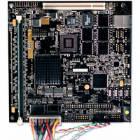
... This section presents the features and block diagram, specifications, and mechanical data for the MPC8349E-mITX-GP board. 1.1 Features This section presents the features, specification, and block diagram of the MPC8349E-mITX-GP board. The features are as follows: • CPU: Freescale MPC8349E running at 533/266 MHz (CPU/CSB (Coherent System Bus)) • ...
Page 3
... The board-level functions discussed in this section are reset, interrupts, and clock distribution. 1.2.1 Reset and Reset Configurations The MPC8349E-mITX-GP reset module generates a single reset to reset the MPC8349E and other peripherals on the board. The reset unit provides power-on reset, hard reset, and soft reset signals in compliance with the MPC8349E hardware specification. ...
Page 4
... Soft reset is generated by the COP/JTAG port. Assertion of SRESET causes the MPC8349E to abort all current internal and external transactions and set most registers to their default values. MPC8349E-mITX-GP Reference Design Platform User’s Guide, Rev 3.3 V MAX811 PORESET to MPC8349E ...
Page 5
... USB over current (USB2_IRQ). The USB2 power supply has an over current detection circuit and generate an interrupt when the current limit reaches (2A thermal shutdown or under voltage lockout (UVLO) condition occurs. This interrupt pin generates an interrupt to IRQ3 of the MPC8349E. MPC8349E-mITX-GP Reference Design Platform User’s Guide, Rev. 0 Freescale Semiconductor External Logic Figure 3. MPC8349E Interrupt Circuitry Figure Preliminary— ...
Page 6
... Figure 4 and Table 1 show the clock distribution on the MPC8349E-mITX-GP board. 25 MHz VSC8201 OSC 24 MHz Crystal USB3300 GND GND Figure 4. MPC8349E-mITX-GP Clock Scheme MPC8349E-mITX-GP Reference Design Platform User’s Guide, Rev 66.666 MHz OSC CLKIN PCI DIV OCCR CFG_CLKIN_DIV GPL5 2 System PLL ...
Page 7
... This approach is used in commodity PC motherboard designs. TT The MPC8349E reads the DIMM SPD data using the DIMM SCL (clock) and the SDA (data) signals through the I2C2 interface. Figure 5 MPC8349E-mITX-GP Reference Design Platform User’s Guide, Rev. 0 Freescale Semiconductor Table 1. Clock Distribution Generated by 66.666 MHz oscillator ...
Page 8
... The on-board single bank 8-Mbyte Flash memory module is connected to the local bus. MPC8349E-mITX-GP Reference Design Platform User’s Guide, Rev VTT 1.25 V ...
Page 9
... ALE LAD[0:15] LBCTL Control Signals 1.2.6 On-Board Flash Memory Through the general-purpose chip-select machine (GPCM), the MPC8349E-mITX-GP provides a total of 8 Mbyte Flash memory using one chip-select signal. The Flash memory is used with the 16-bit port size. J22.E Jumper Off Jumper On The starting address for the Flash bank is 0xFE00_0000 to 0xFE7F_FFFF. ...
Page 10
... There are two PCF8574A I C I/O expander on the MPC8349E-mITX-GP board to provide general purpose I/O expansion via the I2C2 interface. The first PCF8574A (U8) has I2C2 address 0x38 and it is able to control the Green LED (D1) and Yellow LED (D2), set the VSC8201 to powerdown mode. The bit ...
Page 11
... BaseT Interface On the MPC8349E-mITX-GP board, GMII mode is used on TSEC1 , which is connected to the on-board 10/100/1000 PHY (VSC8201). The TSEC I/O voltage is set to 3.3 V. The GMII (1000 BaseT source synchronous bus. For a transmit bus connection synchronous to GTX_CLK from the TSEC module. ...
Page 12
... The MPC8349E has two internal USB modules (USB0 and USB1), a multi-port host (MPH) module, and a dual-role (DR) module. On the MPC8349E-mITX-GP board, USB1 connects to USB PHY (USB3300) through the 8-bit UTMI low pin count interface (ULPI). The USB3300 PHY connects to a USB Mini-AB type receptacle connector that serves as a host/device/OTG USB interface ...
Page 13
... The common on-chip processor (COP) is part of the MPC8349E JTAG module and is implemented as a set of additional instructions and logic. This port can connect to a dedicated emulator for extensive system debugging. Several third-party emulators in the market can connect to the host computer through the MPC8349E-mITX-GP Reference Design Platform User’s Guide, Rev. 0 Freescale Semiconductor Operating Mode ...
Page 14
... Figure 11. PC Figure 11. Connecting the MPC8349E-mITX-GP Board to A Parallel Emulator The 16-pin generic header connector carries the COP/JTAG signals and the additional signals for system debugging. The pinout of this connector is shown in Figure 12. MPC8349E-mITX-GP Board COP Connector MPC8349E-mITX-GP Reference Design Platform User’s Guide, Rev. 0 ...
Page 15
... ABCDEFGH P18 ATX Power Pin 1 1.4 Connectors This section describes the MPC8349E-mITX-GP connectors and their pin assignments. 1.4.1 Case Connector The case connector (J10) connects to the case power switch, power LED, reset switch. • PWR_SW can connect to the 2-pin power push button on the front panel. ...
Page 16
... PCI Slot The MPC8349E-mITX-GP board has one 32-bit 3.3 V PCI expansion slot (P1) for an expansion card. Only the 3.3 V PCI Card is supported. Turn OFF power during insertion and removal of PCI card. MPC8349E-mITX-GP Reference Design Platform User’s Guide, Rev Pin Signal ...
Page 17
... Figure 14. 3.3 V Key on a Typical 3.3 V PCI Card 1.4.4 Fan Connectors There are two fan connectors on the MPC8349E-mITX-GP board, one for powering fan (J9) and the other for powering fan (J5). For typical fans, the red wire is always positive (+) and the black wire is always negative (–). ...
Page 18
... A LGPL0 ON (0) B LGPL1 ON (0) C LGPL3 ON (0) D LGPL5 OFF (1) E BOOT1 OFF(1) MPC8349E-mITX-GP Reference Design Platform User’s Guide, Rev 000 local bus EEPROM (Default) 2 001 I C EEPROM,PCI_CLK/PCI_SYNC_IN 25–44 MHz 2 010 I C EEPROM,PCI_CLK/PCI_SYNC_IN 25–66.666 MHz 011 Hard-coded option, 66 MHz, 266 MHz, 400 MHz (PCI, CSB, CPU) ...
Page 19
... G I2C-WP ON (0) H F_WP OFF (1) Table 9 lists the connectors, jumpers, switches, and LEDs on the MPC8349E-mITX-GP board. Table 9. Lists of Connectors, Jumpers, Switches, and LEDs Reference BT1 Battery holder for RTC J4 Background Debug Mode (BDM). Header for Flash programming and debug of on-board MC9S08QG8 Microcontroller. ...
Page 20
... Flash (U7) top sectors are not write protected (WP not asserted). Jumper On Flash (U7) top sectors are write protected (WP asserted). 1.6.2 EEPROM An on-board serial EEPROM allows storage of miscellaneous board-related data. The EEPROM can be write-protected by S2.SW3, as shown in MPC8349E-mITX-GP Reference Design Platform User’s Guide, Rev Description Switches LEDs Table 10 Description Table 11 ...
Page 21
... PCI Operating Frequency An M66EN input pin determines the AC timing of the PCI interface. On the MPC8349E-mITX-GP board, the state of this signal can be driven the J22 jumper to select 33 MHz AC timing. If J22.F is not driven to 0, the M66EN signal level is determined by the PCI agent card connected to PCI slot P1 MHz only card is inserted, the M66EN signal is driven the PCI agent card according to the PCI specification driven can perform at 66 MHz ...
Page 22
... Field PCIHOST PCI64 PCI1ABR PCI2ABR COREDIS BMS BOOTSEQ SWEN ROMLOC Field TSEC1M TSEC2M Figure 18. Reset Configuration Word High (RCWH) Bit Settings Bits Name 0 LBIUCM 1 DDRCM 2–3 — 4–7 SPMF[0–3] MPC8349E-mITX-GP Reference Design Platform User’s Guide, Rev Figure 17 and Figure 18 SPMF — — ...
Page 23
... Table 14. RCWL Bit Descriptions (continued) Bits Name 4–7 SPMF[0–3] 8 — 9–15 COREPLL [0–6] 9–15 COREPLL [0–6] 16–31 — MPC8349E-mITX-GP Reference Design Platform User’s Guide, Rev. 0 Freescale Semiconductor Meaning System PLL 0110 multiplication 0111 factor 1000 1001 1010 1011 1100 1101 1110 ...
Page 24
... PCI2ARB 3 Reserved 4 COREDIS 5 BMS 6–7 BOOTSEQ 8 SWEN 9–11 ROMLOC 12–15 Reserved 16–17 TSEC1M MPC8349E-mITX-GP Reference Design Platform User’s Guide, Rev Meaning PCI host mode 0 1: Default PCI 64 bit bus 0: Default mode 1 PCI1 arbiter 0 1: Default PCI2 Arbiter 0 1: Default — ...
Page 25
... MHz 0101 66.666 MHz 0100 66.666 MHz 0011 66.666 MHz 0101 66.666 MHz 0100 66.666 MHz 0011 MPC8349E-mITX-GP Reference Design Platform User’s Guide, Rev. 0 Freescale Semiconductor Meaning TSEC2 Mode 00 01 10: Default 10 — Must be cleared True little endian 0: Default 1 ...
Page 26
... The MPC8349E requires a 3.3 V and 5 V power supply from the ATX power connector for normal operation. The 3.3 V power supply is reduced to 1.2 V and 2.5 V. The 1.2 V power is generated from a switching power supply for a CPU core. The 2.5 V power is generated from an LDO regulator for the DDR controller. MPC8349E-mITX-GP Reference Design Platform User’s Guide, Rev ...
Page 27
... Internal bus MPC8349E-mITX-GP Reference Design Platform User’s Guide, Rev. 0 Freescale Semiconductor MIC2505 MAX1953 MIC29302 Figure 20. Power Supply Circuitry during ramp-up and power-down. I/O Chip-Select ...
Page 28
... Addressing: Total address range Flash memory (local bus) DDR SDRAM Operating temperature Storage temperature Relative humidity PCB dimensions: Length Width Thickness MPC8349E-mITX-GP Reference Design Platform User’s Guide, Rev Chip-Select Line Local bus LCS0 Boot Flash (8 Mbyte) Local bus LCS0 Reserved Typical 3 ...
Page 29
... Figure 21. Dimensions of the MPC8349E-mITX-GP Board 2 Getting Started This section describes how to boot up the MPC8349E-mITX-GP board. The on-board Flash memory has been preloaded with a Flash image from the factory. Before powering up the board, set the on-board jumpers according to the settings listed in module according to the instructions in external connections as described in Avoid touching areas of integrated circuitry and connectors ...
Page 30
... Getting Started 2.1 Board Jumper Settings Figure 22 shows the top view of the MPC8349E-mITX-GP with pin 1 marked for each reference. Using Figure guide, the default jumper settings are given in of the board and moving around the board in a clockwise manner. J21 S3 J19 ...
Page 31
... DDR controller. DDR1 unbuffered DIMM modules with fewer than 12 or greater than 14 row addresses are not supported. DIMM modules with fewer than 8 or greater than 11 column addresses are not supported. MPC8349E-mITX-GP Reference Design Platform User’s Guide, Rev. 0 Freescale Semiconductor Table 19 ...
Page 32
... Then connect the AC adaptor as in shown in USB 2.0 Ethernet OTG 10/100/1000 Not Used Connect Serial Port Cable MPC8349E-mITX-GP Reference Design Platform User’s Guide, Rev ROW COLUMN Figure Connect AC Adapter Figure 24. External Connections Preliminary—Subject to Change Without Notice Number 12– ...
Page 33
... Serial Port Configuration (PC) Before powering up the MPC8349E-mITX-GP system, configure the serial port of the attached computer as follows: Data rate: 115.2 Kbps, Number of data bits: 8, Parity: none, Number of Stop bits: 1, Flow Control: Disabled. 2.5 Power Up Press the power button on the front panel. ...
Page 34
... MPC8349E-mITX-GP Software A board support package (BSP) is pre-installed on the MPC8349E-mITX-GP. This BSP consists of a bootloader (u-boot), a generic PPC Linux-based system, and associated file system which reside in the on-board Flash memory. Upon power up, the Linux system is running on the MPC8349E-mITX-GP. ...
Page 35
... LTIB to build the ISO image. 3.1 Third-Party Application Software Many third-party applications are available for the MPC8349E-mITX-GP. They are typically built on top of the original BSP delivered by Freescale. To run demonstrations or to acquire details of Freescale’s third-party applications for this MPC8349E-mITX-GP, contact your local Freescale sales office. ...
Page 36
... Denver, Colorado 80217 1-800-441-2447 303-675-2140 Fax: 303-675-2150 LDCForFreescaleSemiconductor @hibbertgroup.com Document Number: MPC8349EMITXGPUG Rev. 0 10/2006 Preliminary—Subject to Change Without Notice Information in this document is provided solely to enable system and software implementers to use Freescale Semiconductor products. There are no express or implied copyright licenses granted hereunder to design or fabricate any integrated circuits or integrated circuits based on the information in this document ...