STR910-EVAL STMicroelectronics, STR910-EVAL Datasheet - Page 7
STR910-EVAL
Manufacturer Part Number
STR910-EVAL
Description
BOARD EVAL FOR STR910 FAMILY
Manufacturer
STMicroelectronics
Type
MCUr
Specifications of STR910-EVAL
Contents
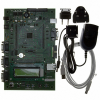
STR910F Evaluation Board, LCD, Microphone, Speaker, and Joystick
Processor To Be Evaluated
STR91xF
Interface Type
RS-232, Ethernet, USB
Silicon Manufacturer
ST Micro
Core Architecture
ARM
Core Sub-architecture
ARM9
Silicon Core Number
STR9
Silicon Family Name
STR91x
Kit Contents
Board
For Use With/related Products
STR91xF
For Use With
497-8268 - BOARD EVAL FOR EVAL-STR910
Lead Free Status / RoHS Status
Contains lead / RoHS non-compliant
Other names
497-5067
Available stocks
Company
Part Number
Manufacturer
Quantity
Price


UM0174
1
Getting started
Your STR910-EVAL is designed with a full range of hardware features that will help you
rapidly evaluate microcontroller peripherals and develop your own applications. Descriptions
of hardware features and configurations are provided in
Demonstration software is preloaded in the board’s flash memory for easy demonstration of
device peripherals in stand-alone mode. For more information refer to the demonstration
software getting started.
Your STR910-EVAL is also designed for use as an application development platform and
reference design, and supports connection to a full range of in-circuit debugging tools and
integrated development environments.
To start using your STR910-EVAL evaluation board for application development, you will
have to set up your development tools and connect to the STR91xF.
1.
2.
3.
Figure 2.
Connect to your STR910-EVAL via the 20-pin JTAG connector.
A 38-pin ETM connector is also provided, allowing you to connect to and use your
microcontroller’s Embedded Trace Macrocell during debugging. For additional
configuration information, see
Power up the evaluation board.
The board can be powered by 5V from either the jack for external power supply, USB
connector, or a daughter board. For additional configuration information, see
Section 2.1 on page
Connect to the device from the debugging software on your host PC.
The BCD files, FME file and installation instructions that you will need to update your
debugging software are available for free download at the STMicroelectronics
microcontrollers support site on www.st.com.
Trace tool / connection
(optional)
Connecting development tools
Optional trace tool connects
to the STR91xF via a 38-pin
ETM connector.
10.
In-circuit emulator
Section 2.12 on page 17
Host PC running your
debugging software /
integrated development
environment
Section 2 on page
In-circuit emulator
connects via 20-pin
JTAG standard
connector
8.
Getting started
7/46
Related parts for STR910-EVAL
Image
Part Number
Description
Manufacturer
Datasheet
Request
R

Part Number:
Description:
MCU 16/32BIT FLASH 128-TQFP
Manufacturer:
STMicroelectronics
Datasheet:
Part Number:
Description:
MCU ARM9 512KB FLASH 128LQFP
Manufacturer:
STMicroelectronics
Datasheet:

Part Number:
Description:
MCU 256KB FLASH 64K RAM 144LFBGA
Manufacturer:
STMicroelectronics
Datasheet:

Part Number:
Description:
MCU 512KB FLASH 96K RAM 128LQFP
Manufacturer:
STMicroelectronics
Datasheet:

Part Number:
Description:
MCU 512KB FLASH 96K RAM 128LQFP
Manufacturer:
STMicroelectronics
Datasheet:
Part Number:
Description:
MCU 512KB FLASH 96K RAM 144LFBGA
Manufacturer:
STMicroelectronics
Datasheet:
Part Number:
Description:
MCU ARM9 2048KB FLASH 128LQFP
Manufacturer:
STMicroelectronics
Datasheet:
Part Number:
Description:
MCU ARM9 1024KB FLASH 128LQFP
Manufacturer:
STMicroelectronics
Datasheet:
Part Number:
Description:
MCU ARM9 2048KB FLASH 128LQFP
Manufacturer:
STMicroelectronics
Datasheet:

Part Number:
Description:
MCU 256KB FLASH 96K RAM 128LQFP
Manufacturer:
STMicroelectronics
Datasheet:

Part Number:
Description:
MCU ARM9 512KB FLASH 80LQFP
Manufacturer:
STMicroelectronics
Datasheet:
Part Number:
Description:
MCU ARM9 512KB FLASH 144LFBGA
Manufacturer:
STMicroelectronics
Datasheet:

Part Number:
Description:
MCU 256KB FLASH 64K RAM 80LQFP
Manufacturer:
STMicroelectronics
Datasheet:

Part Number:
Description:
MCU 256KB FLASH 64K RAM 128LQFP
Manufacturer:
STMicroelectronics
Datasheet:

Part Number:
Description:
MCU 256KB FLASH 96K RAM 80LQFP
Manufacturer:
STMicroelectronics
Datasheet: