STR910-EVAL STMicroelectronics, STR910-EVAL Datasheet - Page 10
STR910-EVAL
Manufacturer Part Number
STR910-EVAL
Description
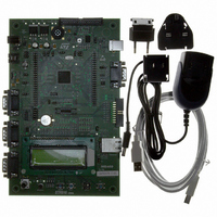
BOARD EVAL FOR STR910 FAMILY
Manufacturer
STMicroelectronics
Type
MCUr
Specifications of STR910-EVAL
Contents
STR910F Evaluation Board, LCD, Microphone, Speaker, and Joystick
Processor To Be Evaluated
STR91xF
Interface Type
RS-232, Ethernet, USB
Silicon Manufacturer
ST Micro
Core Architecture
ARM
Core Sub-architecture
ARM9
Silicon Core Number
STR9
Silicon Family Name
STR91x
Kit Contents
Board
For Use With/related Products
STR91xF
For Use With
497-8268 - BOARD EVAL FOR EVAL-STR910
Lead Free Status / RoHS Status
Contains lead / RoHS non-compliant
Other names
497-5067
Available stocks
Company
Part Number
Manufacturer
Quantity
Price


Hardware layout and configuration
2.1
10/46
The following sections provide jumper settings for configuring your STR910-EVAL
evaluation board and peripherals, including:
●
●
●
●
●
●
●
Two types of jumpers are used on the STR910-EVAL evaluation board:
●
●
Figure 5.
Power supply
STR910-EVAL evaluation board is designed to be powered by a 5V DC power supply. It is
possible to configure the evaluation board to use any of the following three sources for the
power supply:
●
●
●
There is also a 3V button battery, which can be used as a backup power supply for both the
RTC and the internal RAM of the STR91xF microcontroller.
The power supply is configured by setting the related jumpers, JP2, JP3, JP4, JP6 and
JP15 as described in
Power supply
Clock source
Reset source
Ethernet
Audio features
Serial Flash
CAN
3-pin jumpers with two possible positions, for which settings are presented in
schematics in the following sections
2-pin jumpers with two possible settings: Fitted– the circuit is closed, and Not fitted–
the circuit is open (see
5V DC power adapter connected to the power supply jack (CN2, or PSU for Power
Supply Unit on the silk screen).
5V DC power with 500mA limitation via the USB type-B connector (CN3, or USB on
the silk screen).
5V DC power from the daughter board extension connectors (CN5 and CN6, DTB
for Daughter Board on the silk-screen).
Settings for two-pin jumpers
Table
Not fitted
1.
Figure
5)
●
●
●
●
●
●
RS232 and IrDA
Motor control
RTC and tamper
USB
Development and debugging tool support
Display and input devices
Fitted
UM0174
Related parts for STR910-EVAL
Image
Part Number
Description
Manufacturer
Datasheet
Request
R

Part Number:
Description:
MCU 16/32BIT FLASH 128-TQFP
Manufacturer:
STMicroelectronics
Datasheet:
Part Number:
Description:
MCU ARM9 512KB FLASH 128LQFP
Manufacturer:
STMicroelectronics
Datasheet:

Part Number:
Description:
MCU 256KB FLASH 64K RAM 144LFBGA
Manufacturer:
STMicroelectronics
Datasheet:

Part Number:
Description:
MCU 512KB FLASH 96K RAM 128LQFP
Manufacturer:
STMicroelectronics
Datasheet:

Part Number:
Description:
MCU 512KB FLASH 96K RAM 128LQFP
Manufacturer:
STMicroelectronics
Datasheet:
Part Number:
Description:
MCU 512KB FLASH 96K RAM 144LFBGA
Manufacturer:
STMicroelectronics
Datasheet:
Part Number:
Description:
MCU ARM9 2048KB FLASH 128LQFP
Manufacturer:
STMicroelectronics
Datasheet:
Part Number:
Description:
MCU ARM9 1024KB FLASH 128LQFP
Manufacturer:
STMicroelectronics
Datasheet:
Part Number:
Description:
MCU ARM9 2048KB FLASH 128LQFP
Manufacturer:
STMicroelectronics
Datasheet:

Part Number:
Description:
MCU 256KB FLASH 96K RAM 128LQFP
Manufacturer:
STMicroelectronics
Datasheet:

Part Number:
Description:
MCU ARM9 512KB FLASH 80LQFP
Manufacturer:
STMicroelectronics
Datasheet:
Part Number:
Description:
MCU ARM9 512KB FLASH 144LFBGA
Manufacturer:
STMicroelectronics
Datasheet:

Part Number:
Description:
MCU 256KB FLASH 64K RAM 80LQFP
Manufacturer:
STMicroelectronics
Datasheet:

Part Number:
Description:
MCU 256KB FLASH 64K RAM 128LQFP
Manufacturer:
STMicroelectronics
Datasheet:

Part Number:
Description:
MCU 256KB FLASH 96K RAM 80LQFP
Manufacturer:
STMicroelectronics
Datasheet: