STR910-EVAL STMicroelectronics, STR910-EVAL Datasheet
STR910-EVAL
Specifications of STR910-EVAL
Available stocks


Related parts for STR910-EVAL


STR910-EVAL Summary of contents
Page 1
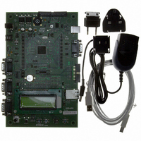
... Introduction The STR910 evaluation board (STR910-EVAL complete development platform for the STMicroelectronic’s ARM STR91xF includes Pre-fetch Queue and Branch cache, full speed USB 2.0 compatible port, Ethernet 100/10 interface, Embedded MAC, CAN2.0B compliant interface Mbyte dual bank Flash memory Kbyte SRAM and many peripherals. ...
Page 2
... Extension connectors for daughter board or wrapping board About the user manuals... This user manual provides information about using your STR910-EVAL and its hardware features. This product includes the STR912FAW47X6 microcontroller with a 2 Mbyte internal Flash memory. Earlier versions of the product include the STR912FAW44X6 microcontroller with a 512 Kbyte internal Flash memory ...
Page 3
UM0174 Contents About the user manuals... . . . . . . . . . . . . . . . . . . . . . . . . . . . . . . . . . . ...
Page 4
Contents 4 Schematics . . . . . . . . . . . . . . . . . . . . . . . . . . . . . . . . . . . . . ...
Page 5
UM0174 List of tables Table 1. Power jumpers . . . . . . . . . . . . . . . . . . . . . . . . . . . . . . . . ...
Page 6
... Figure 14. RS232 connectors (CN10 and CN12, front view Figure 15. Ethernet RJ45 connector (CN11, front view Figure 16. Find the version of your evaluation board Figure 17. STR910-EVAL microcontroller connections . . . . . . . . . . . . . . . . . . . . . . . . . . . . . . . . . . . . 31 Figure 18. Power supply . . . . . . . . . . . . . . . . . . . . . . . . . . . . . . . . . . . . . . . . . . . . . . . . . . . . . . . . . . . 32 Figure 19. CAN and USB connections Figure 20. UART and IrDA connections Figure 21. ...
Page 7
... UM0174 1 Getting started Your STR910-EVAL is designed with a full range of hardware features that will help you rapidly evaluate microcontroller peripherals and develop your own applications. Descriptions of hardware features and configurations are provided in Demonstration software is preloaded in the board’s flash memory for easy demonstration of device peripherals in stand-alone mode ...
Page 8
... The hardware block diagram of the STR910-EVAL of the board relative to the STR91xF peripherals and features on the actual evaluation board. Figure 3. Hardware block diagram Peripheral implementation on the STR910-EVAL board requires the use of alternate pin functions supported by the STR912FAW47X6. A table of alternate pin functions used in this design is provided in 8/46 Appendix A ...
Page 9
... UM0174 Figure 4. STR910-EVAL evaluation board layout Speaker, U5 Daughter board extension connectors, CN5, CN6 Power supply jack, CN2 STR912, U10 IrDA, U9 RS232 with full modem support, CN8 Battery, BT1 RS232 connectors, CN10, CN12 Potentiometer, Microphone, RV2 U21 Tamper_IN, PB1 RESET, PB2 Hardware layout and configuration ...
Page 10
... Figure 5. Settings for two-pin jumpers 2.1 Power supply STR910-EVAL evaluation board is designed to be powered power supply possible to configure the evaluation board to use any of the following three sources for the power supply: ● power adapter connected to the power supply jack (CN2, or PSU for Power Supply Unit on the silk screen). ● ...
Page 11
... Default setting: Fitted Enables consumption measurement of STR91xF backup power supply (VBAT). JP15 Default setting: Fitted The LD1 LED is lit when the STR910-EVAL evaluation board is powered correctly. 2.2 Clock source Four clock sources are available on the STR910-EVAL evaluation board for the microcontroller, USB, RTC and Ethernet PHY transceiver. ...
Page 12
... To use the internal clock of the STR91xF, JP17 is not fitted. In this case P27 can be used for an alternate function. Default setting: Not fitted 2.3 Reset source The reset signal of STR910-EVAL evaluation board is low active. The reset sources include: ● Power On Reset from STM1001 (U7) ● ...
Page 13
... UM0174 2.5 Audio features STR910-EVAL evaluation board supports both audio recording and playback. This can be disabled or enabled by setting of jumpers JP5 and JP26. Audio volume can be adjusted using the potentiometer RV1. Table 4. Audio jumpers Jumper Audio power amplifier TS4871 is forced into standby mode when JP5 (SPEAKER on the silk-screen) is not fitted ...
Page 14
... Default setting: Not fitted 2.8 RS232 and IrDA Three channels for RS232 communication are available on the STR910-EVAL board. Two channels UART2 and UART3, use the RS232 transceiver U14 and two male D-type 9- pin connectors CN10 and CN12. IrDA communication is supported as a multiplex function on UART2 ...
Page 15
... Default setting: Fitted 2.9 Motor control STR910-EVAL board supports induction motor control via a 34-pin connector CN1, which provides all required control and feedback signals to and from a motor power-drive board. Available signals on this connector include emergency stop, motor speed, 3-phase motor current, bus voltage, Heatsink temperature from the motor drive board and 6 channels of PWM control signals going to the motor drive circuit ...
Page 16
... PB1 can be used to simulate a tamper event on the RTC. 2.11 USB The STR910-EVAL evaluation board offers USB 2.0 compliant communication via a USB type-B connector (CN3) with full-speed (12Mb/s) data transfer. The evaluation board and daughter board can be powered from this USB connection with a 500mA current limitation ...
Page 17
... UM0174 2.12 Development and debugging tool support The STR910-EVAL evaluation board supports connection to both In-Circuit Emulators (ICE) via a 20-pin standard JTAG interface and Trace tools via a 38-pin Embedded Trace Macrocell (ETM) interface. To enable the ETM trace feature, some alternate circuit functions have to be disconnected ...
Page 18
... LCD and 4 general purpose LED's (LD2 are available as display devices. A 4-direction joystick with selection key and one general purpose button (PB3) are available as input devices. STR910-EVAL also supports a second optional 2x16 character LCD that can be mounted on the U17 connector. Table 10. ...
Page 19
... UM0174 3 Connectors The following sections provide pin descriptions for the STR910-EVAL evaluation board connectors shown in Figure 6. STR910-EVAL evaluation board connectors USB type B connector CN3 Motor control connector CN1 Power supply connector CN2 Daughter board extension connector CN5 and CN6 Figure 6. CAN type D, 9-pin ...
Page 20
Connectors 3.1 Motor control connector CN1 Figure 7. Motor control connector (CN1, top view) Table 11. Motor control connector (CN1) Pin number 1 EMERGENCY STOP 3 PWM-UH 5 PWM-UL 7 PWM-VH 9 PWM-VL 11 PWM-WH 13 PWM-WL 15 PHASE A ...
Page 21
... UM0174 3.2 Power supply connector CN2 Your STR910-EVAL evaluation board can be powered from power supply via the external power supply jack (CN2) shown in positive. For power supply jumper configurations, refer to section Figure 8. Power supply connector (CN2, front view) 3.3 USB type B connector CN3 Figure 9 ...
Page 22
Connectors 3.4 CAN type D, 9-pin male connector CN4 Figure 10. CAN type D, 9-pin male connector (CN4, front view) Table 13. CAN type D, male 9-pin male connector (CN4) Pin number CANL 3, 6, ...
Page 23
UM0174 Table 14. ETM trace connector (CN7) (continued) Pin number 3.6 RS232 with full modem control CN8 Figure 12. RS232 connector (CN8, front view) Table 15. RS232 connector (CN8) with ...
Page 24
Connectors 3.7 JTAG debug connector CN9 Figure 13. JTAG debug connector (CN9, top view) Table 16. JTAG debug connector (CN9) Pin number 1 3.3V power 3 TRST 5 TDI 7 TMS 9 TCK 11 RTCK 13 TDO 15 nSRST 17 ...
Page 25
UM0174 Table 17. RS232 connectors (CN10, CN12) Pin number UART2_TXD 5 GND UART3_TXD 5 GND 3.9 Ethernet RJ45 connector CN11 Figure 15. Ethernet RJ45 connector (CN11, front view) ...
Page 26
... Daughter board extension connector CN5 and CN6 Two 50-pin male headers CN5 and CN6 can be used to connect a daughter board or standard wrapping board to the STR910-EVAL evaluation board. All 80 GPI/Os and the EMI interface control signals are available on these connectors. Each pin on CN5 and CN6 can be used by a daughter board after disconnecting it from the corresponding function block on the STR910-EVAL evaluation board ...
Page 27
... None - LCD Remove R63 LCD Remove R87 LCD Remove R64 Disconnect STR910-EVAL evaluation board from Motor control motor power drive board ETM Disconnect STR910-EVAL evaluation board from ETM tracer. JP18 is not fitted. UART1 DCD ETM Disconnect STR910-EVAL evaluation board from ETM tracer. JP22 is not fitted. ...
Page 28
... Remove R78 UART3 TX - UART1 TX - UART1 RTS - UART2 TX UART3 RX Remove R75 None - ETM trace Disconnect STR910-EVAL evaluation board from ETM racer. JP17 is not fitted. USB clock LCD Remove R62 LED2 Remove R83 LED0 Remove R81 UM0174 To disconnect from the To disconnect from the ...
Page 29
... P26 46 P93 48 P91 50 GND Note: The D5V pin can be used to power the STR910-EVAL board from the power supply provided by the daughter board. STR910-EVAL function block ETM Trace Disconnect STR910-EVAL evaluation board from ETM trace. JP8 is not fitted. Motor control Ethernet Remove R70 ...
Page 30
... Schematics 4 Schematics This section provides design schematics for the STR910-EVALboard key features, which are provided to help you implement these features in your own application designs. Schematics are provided for: ● STR910F microcontroller connections ● Power supply ● CAN and USB connectors ● ...
Page 31
... UM0174 Figure 17. STR910-EVAL microcontroller connections Schematics 31/46 ...
Page 32
Schematics Figure 18. Power supply 32/46 UM0174 ...
Page 33
UM0174 Figure 19. CAN and USB connections Schematics 33/46 ...
Page 34
Schematics Figure 20. UART and IrDA connections 34/46 UM0174 ...
Page 35
UM0174 Figure 21. Ethernet connection Schematics 35/46 ...
Page 36
Schematics Figure 22. Audio peripherals 36/46 UM0174 ...
Page 37
UM0174 Figure 23. JTAG, ETM and daughter board connections Schematics 37/46 ...
Page 38
Schematics Figure 24. LCD and joystick 38/46 UM0174 ...
Page 39
... Table 21 are used in the application board design. The table indicates the pin functions used for STR910-EVAL peripherals in blue. If you choose to implement the Embedded Trace Module (ETM) connector for your debugging tool, you will use the alternate functions for specific pins that are indicated in gray instead of the function indicated in blue. ...
Page 40
Implemented STR912F pin functions Table 21. Implemented pin functions of the STR912FAW47X6 (continued) Default input Pin # Pin name function UART0_CTS 10 P2.0 Clear To Send UART0_DSR 11 P2.1 Data Set Ready UART0_DCD 33 P2.2 Dat Carrier Det UART0_RI 35 ...
Page 41
UM0174 Table 21. Implemented pin functions of the STR912FAW47X6 (continued) Default input Pin # Pin name function ADC7 124 P4.7 ADC input chnl EXINT8 12 P5.0 External Intr EXINT9 18 P5.1 External Intr PHYCLK EXINT10 25 _P5.2 External Intr EXINT11 ...
Page 42
Implemented STR912F pin functions Table 21. Implemented pin functions of the STR912FAW47X6 (continued) Default input Pin # Pin name function EXINT28 14 P7.4 External Intr EXINT29 15 P7.5 External Intr EXINT30 118 P7.6 External Intr EXINT31 119 P7.7 External Intr ...
Page 43
... Appendix B Product support If you experience any problems with this product you need spare parts or repairs, contact the distributor or the STMicroelectronics sales office where you purchased the product. On the STMicroelectronics microcontrollers support site at www.st.com, you will find a complete listing of ST sales offices and distributors, as well as documentation, software downloads and user discussion groups to help you answer questions and stay up to date with our latest product developments ...
Page 44
Product support Getting prepared before you call Collect the following information about the product before contacting ST or your distributor: 1. Name of the company where you purchased the product. 2. Date of purchase. 3. Order Code: Refer to the ...
Page 45
UM0174 Revision history Table 22. Document revision history Date 12-Apr-2006 17-May-2006 2-Nov-2007 Revision 1 First draft release for review. Added explanation of schematic version numbers Replaced board schematics C.0 with modified schematics C.1. 2 Changes to revision C.1 schematics include: ...
Page 46
... Information in this document is provided solely in connection with ST products. STMicroelectronics NV and its subsidiaries (“ST”) reserve the right to make changes, corrections, modifications or improvements, to this document, and the products and services described herein at any time, without notice. All ST products are sold pursuant to ST’s terms and conditions of sale. ...