STR910-EVAL STMicroelectronics, STR910-EVAL Datasheet - Page 17
STR910-EVAL
Manufacturer Part Number
STR910-EVAL
Description
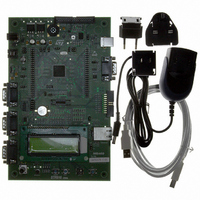
BOARD EVAL FOR STR910 FAMILY
Manufacturer
STMicroelectronics
Type
MCUr
Specifications of STR910-EVAL
Contents
STR910F Evaluation Board, LCD, Microphone, Speaker, and Joystick
Processor To Be Evaluated
STR91xF
Interface Type
RS-232, Ethernet, USB
Silicon Manufacturer
ST Micro
Core Architecture
ARM
Core Sub-architecture
ARM9
Silicon Core Number
STR9
Silicon Family Name
STR91x
Kit Contents
Board
For Use With/related Products
STR91xF
For Use With
497-8268 - BOARD EVAL FOR EVAL-STR910
Lead Free Status / RoHS Status
Contains lead / RoHS non-compliant
Other names
497-5067
Available stocks
Company
Part Number
Manufacturer
Quantity
Price


UM0174
2.12
Development and debugging tool support
The STR910-EVAL evaluation board supports connection to both In-Circuit Emulators (ICE)
via a 20-pin standard JTAG interface and Trace tools via a 38-pin Embedded Trace
Macrocell (ETM) interface.
To enable the ETM trace feature, some alternate circuit functions have to be disconnected
by setting the jumpers listed in
and USB external 48MHz clock use STR91xF I/O pins that are required for the ETM trace
connection on CN7. These features will be restricted when ETM trace is used. The
evaluation board can not be connected to a motor control drive board on connector CN1.
To ensure the integrity of high-speed signals on the ETM trace connections, each ETM
signal should have a single point-to-point connection from STR91xF microcontroller to the
38-pin ETM connector. Stub tracks ("dead-end" extensions to the signal track) should be
eliminated. If you encounter problems when using ETM connector, you can remove the
resistors indicated in
connection.
Table 9.
6
10
24
26
28
30
32
34
36
38
Pin on CN7
ETM trace configuration
TRACECLK
EXTTRIG
TRACEPKT[3]
TRACEPKT[2]
TRACEPKT[1]
TRACEPKT[0]
TRACESYNC
PIPESTAT[2]
PIPESTAT[1]
PIPESTAT[0]
Description
Table 9
to avoid stub and improve signal quality on the ETM
Disconnect motor power drive board
connected to CN1
Keep JP16 set as shown below:
JP22 is not fitted (UART1 RI signal is
disabled)
JP18 is not fitted (UART1 DCD signal is
disabled)
JP19 is not fitted (UART1 DSR signal is
disabled)
JP21 is not fitted (UART1 CTS signal is
disabled)
JP17 is not fitted (external USB48MHz clock
P27 source is disable)
No
JP8 is not fitted (Motor control Encoder A pin
on CN1 connector is disabled)
No
Table
9. Motor control, UART1 full modem control support
To disable alternate function
1
2
Hardware layout and configuration
Remove R34
No change
Remove R35
Remove R36
Remove R37
Remove R38
Remove R39
Remove R40
Remove R41
Remove R42
To avoid stub
17/46
Related parts for STR910-EVAL
Image
Part Number
Description
Manufacturer
Datasheet
Request
R

Part Number:
Description:
MCU 16/32BIT FLASH 128-TQFP
Manufacturer:
STMicroelectronics
Datasheet:
Part Number:
Description:
MCU ARM9 512KB FLASH 128LQFP
Manufacturer:
STMicroelectronics
Datasheet:

Part Number:
Description:
MCU 256KB FLASH 64K RAM 144LFBGA
Manufacturer:
STMicroelectronics
Datasheet:

Part Number:
Description:
MCU 512KB FLASH 96K RAM 128LQFP
Manufacturer:
STMicroelectronics
Datasheet:

Part Number:
Description:
MCU 512KB FLASH 96K RAM 128LQFP
Manufacturer:
STMicroelectronics
Datasheet:
Part Number:
Description:
MCU 512KB FLASH 96K RAM 144LFBGA
Manufacturer:
STMicroelectronics
Datasheet:
Part Number:
Description:
MCU ARM9 2048KB FLASH 128LQFP
Manufacturer:
STMicroelectronics
Datasheet:
Part Number:
Description:
MCU ARM9 1024KB FLASH 128LQFP
Manufacturer:
STMicroelectronics
Datasheet:
Part Number:
Description:
MCU ARM9 2048KB FLASH 128LQFP
Manufacturer:
STMicroelectronics
Datasheet:

Part Number:
Description:
MCU 256KB FLASH 96K RAM 128LQFP
Manufacturer:
STMicroelectronics
Datasheet:

Part Number:
Description:
MCU ARM9 512KB FLASH 80LQFP
Manufacturer:
STMicroelectronics
Datasheet:
Part Number:
Description:
MCU ARM9 512KB FLASH 144LFBGA
Manufacturer:
STMicroelectronics
Datasheet:

Part Number:
Description:
MCU 256KB FLASH 64K RAM 80LQFP
Manufacturer:
STMicroelectronics
Datasheet:

Part Number:
Description:
MCU 256KB FLASH 64K RAM 128LQFP
Manufacturer:
STMicroelectronics
Datasheet:

Part Number:
Description:
MCU 256KB FLASH 96K RAM 80LQFP
Manufacturer:
STMicroelectronics
Datasheet: