STR910-EVAL STMicroelectronics, STR910-EVAL Datasheet - Page 16
STR910-EVAL
Manufacturer Part Number
STR910-EVAL
Description
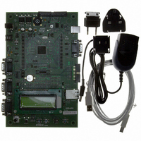
BOARD EVAL FOR STR910 FAMILY
Manufacturer
STMicroelectronics
Type
MCUr
Specifications of STR910-EVAL
Contents
STR910F Evaluation Board, LCD, Microphone, Speaker, and Joystick
Processor To Be Evaluated
STR91xF
Interface Type
RS-232, Ethernet, USB
Silicon Manufacturer
ST Micro
Core Architecture
ARM
Core Sub-architecture
ARM9
Silicon Core Number
STR9
Silicon Family Name
STR91x
Kit Contents
Board
For Use With/related Products
STR91xF
For Use With
497-8268 - BOARD EVAL FOR EVAL-STR910
Lead Free Status / RoHS Status
Contains lead / RoHS non-compliant
Other names
497-5067
Available stocks
Company
Part Number
Manufacturer
Quantity
Price


Hardware layout and configuration
Note:
2.10
2.11
16/46
Table 7.
When using the motor control connector, ensure that JP9 is set to allow the use of P0.1 on
the STR910F for motor control. JP9 can be configured to use P0.1 for the USB peripheral.
See
RTC and tamper
A 32KHz crystal X2 is available for the embedded RTC inside the STR91xF. The push
button PB1 can be used to simulate a tamper event on the RTC.
USB
The STR910-EVAL evaluation board offers USB 2.0 compliant communication via a USB
type-B connector (CN3) with full-speed (12Mb/s) data transfer. The evaluation board and
daughter board can be powered from this USB connection at 5V DC with a 500mA current
limitation.
Two clock sources are available for USB:
●
●
Clock source is selected by setting JP17. Refer to
configuration details.
The unplugging of hardware from the USB connector (CN3) can be simulated by your
application software. USB hardware disconnect simulation is enabled by configuring the
jumper JP9, as described in
Table 8.
JP8
JP9
Jumper
Jumper
Table 8 on page
PLL generated clock from the STR91xF
External oscillator U12
Motor control jumpers (continued)
USB jumpers
STR91xF I/O pin P25 is used as external clock of timer for motor control when JP8 is
fitted. P25 can be used by a daughter board when JP8 is not fitted.
Default setting: Fitted
JP9 can be used to enable USB hardware disconnect simulation using P0.1 on the
STR910F. P0.1 of the STR91xF can be used either for Motor Control or USB.
USB hardware disconnect simulation is enabled and P0.1 of the
STR910F is used by the USB peripheral when JP9 is set as
shown to the right:
In this case, the USB pull up resistor (R10) is connected to pin 3
of the USB connector.
USB hardware disconnect simulation is disabled, and P0.1 of
the STR910F is used by the Motor Control connector (C1) when
JP9 is set as shown to the right:
(Default setting)
16.
Table
8.
Description
Description
Table 2: Clock jumpers on page 12
1
1
UM0174
for
2
2
Related parts for STR910-EVAL
Image
Part Number
Description
Manufacturer
Datasheet
Request
R

Part Number:
Description:
MCU 16/32BIT FLASH 128-TQFP
Manufacturer:
STMicroelectronics
Datasheet:
Part Number:
Description:
MCU ARM9 512KB FLASH 128LQFP
Manufacturer:
STMicroelectronics
Datasheet:

Part Number:
Description:
MCU 256KB FLASH 64K RAM 144LFBGA
Manufacturer:
STMicroelectronics
Datasheet:

Part Number:
Description:
MCU 512KB FLASH 96K RAM 128LQFP
Manufacturer:
STMicroelectronics
Datasheet:

Part Number:
Description:
MCU 512KB FLASH 96K RAM 128LQFP
Manufacturer:
STMicroelectronics
Datasheet:
Part Number:
Description:
MCU 512KB FLASH 96K RAM 144LFBGA
Manufacturer:
STMicroelectronics
Datasheet:
Part Number:
Description:
MCU ARM9 2048KB FLASH 128LQFP
Manufacturer:
STMicroelectronics
Datasheet:
Part Number:
Description:
MCU ARM9 1024KB FLASH 128LQFP
Manufacturer:
STMicroelectronics
Datasheet:
Part Number:
Description:
MCU ARM9 2048KB FLASH 128LQFP
Manufacturer:
STMicroelectronics
Datasheet:

Part Number:
Description:
MCU 256KB FLASH 96K RAM 128LQFP
Manufacturer:
STMicroelectronics
Datasheet:

Part Number:
Description:
MCU ARM9 512KB FLASH 80LQFP
Manufacturer:
STMicroelectronics
Datasheet:
Part Number:
Description:
MCU ARM9 512KB FLASH 144LFBGA
Manufacturer:
STMicroelectronics
Datasheet:

Part Number:
Description:
MCU 256KB FLASH 64K RAM 80LQFP
Manufacturer:
STMicroelectronics
Datasheet:

Part Number:
Description:
MCU 256KB FLASH 64K RAM 128LQFP
Manufacturer:
STMicroelectronics
Datasheet:

Part Number:
Description:
MCU 256KB FLASH 96K RAM 80LQFP
Manufacturer:
STMicroelectronics
Datasheet: