AC244006 Microchip Technology, AC244006 Datasheet - Page 48
AC244006
Manufacturer Part Number
AC244006
Description
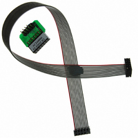
KIT MPLAB REAL ICE TRACE
Manufacturer
Microchip Technology
Datasheet
1.AC244006.pdf
(72 pages)
Specifications of AC244006
Accessory Type
Interface Board
Features
Instruction Trace Capability, Polarized Interface
For Use With
PIC32MX Plug-in Modules
Lead Free Status / RoHS Status
Lead free / RoHS Compliant
For Use With/related Products
PIC32
Lead Free Status / RoHS Status
Lead free / RoHS Compliant
Available stocks
Company
Part Number
Manufacturer
Quantity
Price
Company:

Part Number:
AC244006
Manufacturer:
Microchip Technology
Quantity:
135


7.6
DS51616A-page 44
STANDARD COMMUNICATION BOARD
®
The electrical specifications for logic probes are listed in Table 7-2.
TABLE 7-2:
For standard emulator communication with a target (Section 2.4.1 “Standard
Communication”), use the standard driver board.
The standard driver board is the main interface to the target processor. It contains the
connections to the high voltage (V
required for programming and connecting with the target devices.
The V
down to 0 volts to satisfy the voltage requirements for the specific emulation processor.
The V
actual power comes from the MPLAB REAL ICE in-circuit emulation system as the V
sense line is used as a reference only to track the target voltage. The V
is isolated with an optical switch.
The clock and data connections are interfaces with the following characteristics.
• Clock and data signals are in high-impedance mode (even when no power is
• Clock and data signals are protected from high voltages caused by faulty targets
• Clock and data signals are protected from high current caused from electrical
FIGURE 7-2:
Logic Inputs
Logic Outputs
applied to the MPLAB REAL ICE in-circuit emulator system)
systems, or improper connections
shorts in faulty target systems
Note:
PP
DD
high-voltage lines can produce a variable voltage that can swing from 14V
sense connection draws very little current from the target processor. The
When using the standard driver board, the rate for real-time streaming data
and tracing is limited to 20 MIPS.
™
LOGIC PROBE ELECTRICAL SPECIFICATIONS
V
V
V
V
V
IH
IL
OH
OL
DD
Standard Socket
= V
6-PIN STANDARD PINOUT
1
= V
= 0.55V max V
= 5V
= 3.8V min
2
DD
3
DD
4
5
x 0.3V (max)
x 0.7V (min)
6
Bottom of
Target Board
PP
V
V
OH
OL
), V
DD
= 0.55V max V
= 3V
= 2.4V min
DD
sense lines, and clock and data connections
1
2
3
4
5
6
Pin
V
V
OH
OL
DD
Vpp
Vdd_TGT Power on target
GND
ICSPDAT Standard Com Data
ICSPCLK Standard Com Clock
AUX
Name
= 0.3V max
= 2.3V
= 1.9V min
© 2006 Microchip Technology Inc.
Power
Ground
Auxiliary
Function
V
V
V
OH
OL
DD
DD
= 0.45V max
= 1.65V
= 1.2V min
connection
DD
Related parts for AC244006
Image
Part Number
Description
Manufacturer
Datasheet
Request
R

Part Number:
Description:
Manufacturer:
Microchip Technology Inc.
Datasheet:
Part Number:
Description:
Manufacturer:
Microchip Technology Inc.
Datasheet:
Part Number:
Description:
Manufacturer:
Microchip Technology Inc.
Datasheet:
Part Number:
Description:
Manufacturer:
Microchip Technology Inc.
Datasheet:
Part Number:
Description:
Manufacturer:
Microchip Technology Inc.
Datasheet:
Part Number:
Description:
Manufacturer:
Microchip Technology Inc.
Datasheet:
Part Number:
Description:
Manufacturer:
Microchip Technology Inc.
Datasheet:
Part Number:
Description:
Manufacturer:
Microchip Technology Inc.
Datasheet: