AC244006 Microchip Technology, AC244006 Datasheet - Page 23
AC244006
Manufacturer Part Number
AC244006
Description
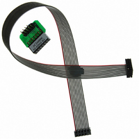
KIT MPLAB REAL ICE TRACE
Manufacturer
Microchip Technology
Datasheet
1.AC244006.pdf
(72 pages)
Specifications of AC244006
Accessory Type
Interface Board
Features
Instruction Trace Capability, Polarized Interface
For Use With
PIC32MX Plug-in Modules
Lead Free Status / RoHS Status
Lead free / RoHS Compliant
For Use With/related Products
PIC32
Lead Free Status / RoHS Status
Lead free / RoHS Compliant
Available stocks
Company
Part Number
Manufacturer
Quantity
Price
Company:

Part Number:
AC244006
Manufacturer:
Microchip Technology
Quantity:
135


2.8
© 2006 Microchip Technology Inc.
PROGRAM MODE
Typically, in order to find out if an application program will run correctly, a breakpoint is
set early in the program code. When a breakpoint is set from the user interface of
MPLAB IDE, the address of the breakpoint is stored in the special internal debug
registers of the target device. Commands on PGC and PGD communicate directly to
these registers to set the breakpoint address.
Next, the Debugger>Run function or the Run icon (forward arrow) is usually pressed
from MPLAB IDE. The emulator will raise the V
the target will start from the Reset vector and execute until the Program Counter
reaches the breakpoint address previously stored in the internal debug registers.
After the instruction at the breakpoint address is executed, the in-circuit debug
mechanism of the target device “fires” and transfers the device’s Program Counter to
the debug executive (much like an interrupt) and the user’s application is effectively
halted. The emulator communicates with the debug executive via PGC and PGD, gets
the breakpoint status information and sends it back to MPLAB IDE. MPLAB IDE then
sends a series of queries to the emulator to get information about the target device,
such as file register contents and the state of the CPU. These queries are ultimately
performed by the debug executive.
The debug executive runs just like an application in program memory. It uses some
locations on the stack (usually just one or two) and, typically, about fourteen file
registers for its temporary variables. If the device does not run, for whatever reason,
such as no oscillator, a faulty power supply connection, shorts on the target board, etc.,
then the debug executive cannot communicate to the MPLAB REAL ICE in-circuit
emulator and MPLAB IDE will issue an error message.
Another way to get a breakpoint is to press the MPLAB IDE’s Halt button (the “pause”
symbol to the right of the Run arrow). This toggles the PGC and PGD lines so that the
in-circuit debug mechanism of the target device switches the Program Counter from the
user’s code in program memory to the debug executive. Again, the target application
program is effectively halted, and MPLAB IDE uses the emulator communications with
the debug executive to interrogate the state of the target device.
When using the Programmer>Program selection to program a device, MPLAB IDE will
disable the in-circuit debug registers so the MPLAB REAL ICE in-circuit emulator will
program only the target application code and the Configuration bits (and EEPROM
data, if available and selected) into the target device. The debug executive will not be
loaded. In this mode the emulator can only toggle the MCLR line to reset and start the
target. A breakpoint cannot be set, and register contents cannot be seen or altered.
The MPLAB REAL ICE in-circuit emulator system programs the target using ICSP. No
clock is required while programming, and all modes of the processor can be
programmed, including code protect, Watchdog Timer enabled and table read protect.
Note:
A header board is required to debug some devices. These parts can be
programmed without the header by connecting the V
lines as described previously.
PP
/MCLR line to allow the target to run,
PP
, PGC and PGD
DS51616A-page 19
Related parts for AC244006
Image
Part Number
Description
Manufacturer
Datasheet
Request
R

Part Number:
Description:
Manufacturer:
Microchip Technology Inc.
Datasheet:
Part Number:
Description:
Manufacturer:
Microchip Technology Inc.
Datasheet:
Part Number:
Description:
Manufacturer:
Microchip Technology Inc.
Datasheet:
Part Number:
Description:
Manufacturer:
Microchip Technology Inc.
Datasheet:
Part Number:
Description:
Manufacturer:
Microchip Technology Inc.
Datasheet:
Part Number:
Description:
Manufacturer:
Microchip Technology Inc.
Datasheet:
Part Number:
Description:
Manufacturer:
Microchip Technology Inc.
Datasheet:
Part Number:
Description:
Manufacturer:
Microchip Technology Inc.
Datasheet: