AC244006 Microchip Technology, AC244006 Datasheet - Page 21
AC244006
Manufacturer Part Number
AC244006
Description
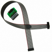
KIT MPLAB REAL ICE TRACE
Manufacturer
Microchip Technology
Datasheet
1.AC244006.pdf
(72 pages)
Specifications of AC244006
Accessory Type
Interface Board
Features
Instruction Trace Capability, Polarized Interface
For Use With
PIC32MX Plug-in Modules
Lead Free Status / RoHS Status
Lead free / RoHS Compliant
For Use With/related Products
PIC32
Lead Free Status / RoHS Status
Lead free / RoHS Compliant
Available stocks
Company
Part Number
Manufacturer
Quantity
Price
Company:

Part Number:
AC244006
Manufacturer:
Microchip Technology
Quantity:
135


2.6
2.7
© 2006 Microchip Technology Inc.
DEBUG MODE
REQUIREMENTS FOR DEBUG MODE
There are two steps to using the MPLAB REAL ICE in-circuit emulator system as a
debugger. The first requires that an application be programmed into the target device.
The second uses the internal in-circuit debug hardware of the target Flash device to run
and test the application program. These two steps are directly related to the MPLAB
IDE operations:
1. Programming the code into the target and activating special debug functions
2. Using the emulator to set breakpoints and run.
If the target device cannot be programmed correctly, the MPLAB REAL ICE in-circuit
emulator will not be able to debug.
Figure 2-12 shows the basic interconnections required for programming. Note that this
is the same as Figure 2-8, but for the sake of clarity, the V
emulator are not shown.
FIGURE 2-12:
A simplified diagram of some of the internal interface circuitry of the MPLAB REAL ICE
in-circuit emulator pod is shown. For programming, no clock is needed on the target
device, but power must be supplied. When programming, the emulator puts
programming levels on V
verify that the part has been programmed correctly, clocks are sent to PGC and data is
read back from PGD. This conforms to the ICSP protocol of the device under
development.
To debug (set breakpoints, see registers, etc.) with the MPLAB REAL ICE in-circuit
emulator system, there are critical elements that must be working correctly:
• The emulator must be connected to a PC. It must be powered by the PC via the
• The emulator must be connected as shown to the V
• The target device must have power and a functional, running oscillator. If the
USB cable, and it must be communicating with MPLAB IDE software via the USB
cable. See Chapter 3. “Installation” for details.
target device with the modular interface cable (or equivalent). V
also required to be connected between the emulator and target device.
target device does not run, for whatever reason, the MPLAB REAL ICE in-circuit
emulator cannot debug.
(see the next section for details).
+5V
Programming
Voltage
PROPER CONNECTIONS FOR PROGRAMMING
Internal Circuits
PP
, sends clock pulses on PGC and serial data via PGD. To
4.7 kΩ
4.7 kΩ
1
5
4
PP
, PGC and PGD pins of the
V
V
PGC
PGD
V
DD
DD
PP
SS
/MCLR
and V
SS
SS
and V
DS51616A-page 17
lines from the
DD
are
Related parts for AC244006
Image
Part Number
Description
Manufacturer
Datasheet
Request
R

Part Number:
Description:
Manufacturer:
Microchip Technology Inc.
Datasheet:
Part Number:
Description:
Manufacturer:
Microchip Technology Inc.
Datasheet:
Part Number:
Description:
Manufacturer:
Microchip Technology Inc.
Datasheet:
Part Number:
Description:
Manufacturer:
Microchip Technology Inc.
Datasheet:
Part Number:
Description:
Manufacturer:
Microchip Technology Inc.
Datasheet:
Part Number:
Description:
Manufacturer:
Microchip Technology Inc.
Datasheet:
Part Number:
Description:
Manufacturer:
Microchip Technology Inc.
Datasheet:
Part Number:
Description:
Manufacturer:
Microchip Technology Inc.
Datasheet: