HSC-ADC-EVALCZ Analog Devices Inc, HSC-ADC-EVALCZ Datasheet - Page 3
HSC-ADC-EVALCZ
Manufacturer Part Number
HSC-ADC-EVALCZ
Description
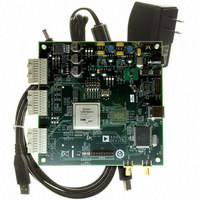
KIT EVAL ADC FIFO HI SPEED
Manufacturer
Analog Devices Inc
Datasheets
1.HSC-ADC-EVALB-DCZ.pdf
(28 pages)
2.HSC-ADC-EVALCZ.pdf
(32 pages)
3.HSC-ADC-EVALCZ.pdf
(40 pages)
Specifications of HSC-ADC-EVALCZ
Design Resources
EVALC PC Board Gerber File
Accessory Type
ADC Interface Board
Silicon Manufacturer
Analog Devices
Application Sub Type
ADC
Kit Application Type
Data Converter
Features
Buffer Memory Board For Capturing Digital Data, USB Port Interface, Windows 98, Windows 2000
Kit Contents
ADC Analyzer, Buffer Memory Board
Rohs Compliant
Yes
Lead Free Status / RoHS Status
Lead free / RoHS Compliant
For Use With/related Products
Single ADC Version
Lead Free Status / Rohs Status
Supplier Unconfirmed
Available stocks
Company
Part Number
Manufacturer
Quantity
Price
Company:

Part Number:
HSC-ADC-EVALCZ
Manufacturer:
Analog Devices Inc
Quantity:
135


FIFO EVALUATION BOARD EASY START
REQUIREMENTS
•
•
•
•
•
•
•
EASY START STEPS
Note: You need administrative rights for the Windows
operating systems during the entire easy start procedure.
It is recommended to complete every step before reverting
to a normal user mode.
1.
2.
3.
4.
5.
FIFO evaluation board, ADC Analyzer, and USB cable
High speed ADC evaluation board and ADC data sheet
Power supply for ADC evaluation board
Analog signal source and appropriate filtering
Low jitter clock source applicable for specific ADC
PC running Windows 98 (2nd ed.), Windows 2000,
PC with a USB 2.0 port recommended (USB 1.1-
Install ADC Analyzer from the CD provided in the FIFO
Connect the FIFO evaluation board to the ADC evaluation
Connect the provided USB cable to the FIFO evaluation
Refer to Table 5 for any jumper changes. Most evaluation
After verification, connect the appropriate power supplies
evaluation, typically <1 ps rms
Windows Me, or Windows XP
compatible)
evaluation kit or download the latest version on the Web.
For the latest updates to the software, check the Analog
Devices website at www.analog.com/hsc-FIFO.
board. If an adapter is required, insert the adapter between
the ADC evaluation board and the FIFO board. If using
the HSC-ADC-EVALB-SC model, connect the evaluation
board to the bottom two rows of the 120-pin connector,
closest to the installed IDT FIFO chip. If using an ADC
with a SPI interface, remove the two 4-pin corner keys so
that the third row can be connected.
board and to an available USB port on the computer.
boards can be used with the default settings.
to the ADC evaluation boards. The FIFO evaluation board
is supplied with a wall mount switching power supply that
provides a 6 V, 2 A maximum output. Connect the supply
end to the rated 100 ac to 240 ac wall outlet at 47 Hz to
63 Hz. The other end is a 2.1 mm inner diameter jack that
connects to the PCB at J301. Refer to the instructions
included in the
about the ADC evaluation board’s power supply and other
requirements.
ADC data sheet
for more information
Rev. 0 | Page 3 of 28
HSC-ADC-EVALB-SC/HSC-ADC-EVALB-DC
6.
7.
8.
9.
10. Start ADC Analyzer.
11. Choose an existing configuration file for the ADC
12. Click Time Data in ADC Analyzer (left-most button under
Once the cable is connected to both the computer and the
(Optional) Verify in the device manager that Analog
Apply power to the evaluation board and check the voltage
Connect the appropriate analog input (which should be
FIFO board, and power is supplied, the USB drivers start
to install. To complete the total installation of the FIFO
drivers, you need to complete the new hardware sequence
two times. The first Found New Hardware Wizard opens
with the text message This wizard helps you install
software for…Pre-FIFO 4.1. Click the recommended
install, and go to the next screen. A hardware installation
warning window should then be displayed. Click Continue
Anyway. The next window that opens should finish the Pre-
FIFO 4.1 installation. Click Finish. Your computer should
go through a second Found New Hardware Wizard, and
the text message, This wizard helps you install software
for…Analog Devices FIFO 4.1, should be displayed.
Continue as you did in the previous installation and click
Continue Anyway. Then click Finish on the next two
windows. This completes the installation.
Devices, FIFO4.1 is listed under the USB hardware.
levels at the board level.
filtered with a band-pass filter) and low jitter clock signal.
Make sure the evaluation boards are powered on before
connecting the analog input and clock.
evaluation board or create one.
the menus). A reconstruction of the analog input is
displayed. If the expected signal does not appear, or if there
is only a flat red line, refer to the ADC Analyzer data sheet
at
www.analog.com/hsc-FIFO
for more information.
Related parts for HSC-ADC-EVALCZ
Image
Part Number
Description
Manufacturer
Datasheet
Request
R

Part Number:
Description:
KIT EVAL ADC FIFO DUAL-CH USB HS
Manufacturer:
Analog Devices Inc
Datasheet:

Part Number:
Description:
KIT EVAL ADC USB FIFO HI-SPEED
Manufacturer:
Analog Devices Inc
Datasheet:

Part Number:
Description:
BOARD FPGA OCTAL LVDS FOR ADC
Manufacturer:
Analog Devices Inc
Datasheet:
Part Number:
Description:
KIT EVAL FOR SINGLE CHAN HSC ADC
Manufacturer:
Analog Devices Inc

Part Number:
Description:
KIT EVAL FOR DUAL ADC/CONV
Manufacturer:
Analog Devices Inc
Datasheet:
Part Number:
Description:
KIT EVAL ADC USB FIFO HI-SPEED
Manufacturer:
Analog Devices Inc
Datasheet:

Part Number:
Description:
KIT EVAL ADC USB FIFO HI-SPEED
Manufacturer:
Analog Devices Inc
Datasheet:
Part Number:
Description:
KIT EVAL ADC FIFO DUAL-CH USB HS
Manufacturer:
Analog Devices Inc
Datasheet:
Part Number:
Description:
BOARD FPGA QUAD LVDS FOR ADC
Manufacturer:
Analog Devices Inc
Datasheet:
Part Number:
Description:
Adapter For AD922x Family
Manufacturer:
Analog Devices Inc
Datasheet:
Part Number:
Description:
Interposer Quad/octal ADCs
Manufacturer:
Analog Devices Inc
Datasheet:

Part Number:
Description:
±1.7g Dual-Axis IMEMS Accelerometer Evaluation Board
Manufacturer:
Analog Devices Inc
Datasheet:

Part Number:
Description:
IC MULTIPLIER ANALOG 8-SOIC T/R
Manufacturer:
Analog Devices Inc
Datasheet:
Part Number:
Description:
IC ANALOG MULTIPLIER 8-DIP
Manufacturer:
Analog Devices Inc
Datasheet: