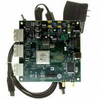
HSC-ADC-EVALCZ Analog Devices Inc, HSC-ADC-EVALCZ Datasheet - Page 13

HSC-ADC-EVALCZ
Manufacturer Part Number
HSC-ADC-EVALCZ
Description
KIT EVAL ADC FIFO HI SPEED
Manufacturer
Analog Devices Inc
Datasheets
1.HSC-ADC-EVALB-DCZ.pdf
(28 pages)
2.HSC-ADC-EVALCZ.pdf
(32 pages)
3.HSC-ADC-EVALCZ.pdf
(40 pages)
Specifications of HSC-ADC-EVALCZ
Design Resources
EVALC PC Board Gerber File
Accessory Type
ADC Interface Board
Silicon Manufacturer
Analog Devices
Application Sub Type
ADC
Kit Application Type
Data Converter
Features
Buffer Memory Board For Capturing Digital Data, USB Port Interface, Windows 98, Windows 2000
Kit Contents
ADC Analyzer, Buffer Memory Board
Rohs Compliant
Yes
Lead Free Status / RoHS Status
Lead free / RoHS Compliant
For Use With/related Products
Single ADC Version
Lead Free Status / Rohs Status
Supplier Unconfirmed
Available stocks
Company
Part Number
Manufacturer
Quantity
Price
Company:
Part Number:
HSC-ADC-EVALCZ
Manufacturer:
Analog Devices Inc
Quantity:
135
EVALUATION BOARD
The FIFO provides all of the support circuitry required to
accept two channels of an ADC’s digital parallel CMOS outputs.
Each of the various functions and configurations can be selected by
proper connection of various jumpers (see Table 5). When
using this in conjunction with an ADC evaluation board, it is
critical that the signal sources used for the analog input and
clock have very low phase noise (<1 ps rms jitter) to realize the
ultimate performance of the converter. Proper filtering of the
analog input signal to remove harmonics and lower the integrated
or broadband noise at the input is also necessary to achieve the
specified noise performance.
See Figure 5 to Figure 15 for complete schematics and layout plots.
POWER SUPPLIES
The FIFO board is supplied with a wall mount switching power
supply that provides a 6 V, 2 A maximum output. Connect the
supply to the rated 100 ac to 240 ac wall outlet at 47 Hz to 63 Hz.
The other end is a 2.1 mm inner diameter jack that connects to
the PCB at J301. On the PC board, the 6 V supply is then fused
and conditioned before connecting to the low dropout 3.3 V
linear regulator that supplies the proper bias to the entire board.
WALL OUTLET
100V TO 240V AC
47Hz TO 63Hz
ROHDE & SCHWARZ,
ROHDE & SCHWARZ,
2V p-p SIGNAL
SYNTHESIZER
2V p-p SIGNAL
SYNTHESIZER
SMHU,
SMHU,
Figure 4. Example Setup Using Quad ADC Evaluation Board and FIFO Data Capture Board
SWITCHING
POWER
SUPPLY
BAND-PASS
FILTER
XFMR
INPUT
CLK
EVALUATION
Rev. 0 | Page 13 of 28
BOARD
PARALLEL
PARALLEL
OUTPUTS
OUTPUTS
CMOS
CMOS
CHB
CHB
SPI
2A MAX
6V DC
HSC-ADC-EVALB-SC/HSC-ADC-EVALB-DC
When operating the evaluation board in a non-default
condition, J316 can be removed to disconnect the switching
power supply. This enables the user to bias the board
independently. Use P302 to connect an independent supply to
the board. A 3.3 V supply is needed with at least a 1 A current
capability.
CONNECTION AND SETUP
The FIFO board has a 120-pin (40-pin, triple row) connector
that accepts two 16-bit channels of parallel CMOS inputs (see
Figure 6). For those ADC evaluation boards that have only an
80-pin (40-pin, double row) connector, it is pertinent for the
lower two rows of the FIFO’s triple row connector to be connected
in order for the data to pass to either FIFO channel correctly.
The top or third row is used to pass SPI signals across to the
adjacent ADC evaluation board that supports this feature.
HSC-ADC-EVALB-DC
FIFO DATA
CAPTURE
BOARD
–
CONNECTION
3.3V
SPI
+
USB
SPI
ANALYZER
RUNNING
ADC
PC


