HSC-ADC-EVALCZ Analog Devices Inc, HSC-ADC-EVALCZ Datasheet - Page 11
HSC-ADC-EVALCZ
Manufacturer Part Number
HSC-ADC-EVALCZ
Description
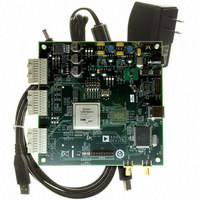
KIT EVAL ADC FIFO HI SPEED
Manufacturer
Analog Devices Inc
Datasheets
1.HSC-ADC-EVALB-DCZ.pdf
(28 pages)
2.HSC-ADC-EVALCZ.pdf
(32 pages)
3.HSC-ADC-EVALCZ.pdf
(40 pages)
Specifications of HSC-ADC-EVALCZ
Design Resources
EVALC PC Board Gerber File
Accessory Type
ADC Interface Board
Silicon Manufacturer
Analog Devices
Application Sub Type
ADC
Kit Application Type
Data Converter
Features
Buffer Memory Board For Capturing Digital Data, USB Port Interface, Windows 98, Windows 2000
Kit Contents
ADC Analyzer, Buffer Memory Board
Rohs Compliant
Yes
Lead Free Status / RoHS Status
Lead free / RoHS Compliant
For Use With/related Products
Single ADC Version
Lead Free Status / Rohs Status
Supplier Unconfirmed
Available stocks
Company
Part Number
Manufacturer
Quantity
Price
Company:

Part Number:
HSC-ADC-EVALCZ
Manufacturer:
Analog Devices Inc
Quantity:
135


JUMPERS
Use the legends in Table 3 and Table 4 to configure the jumpers. On the FIFO evaluation board, Channel A is associated with the bottom
IDT FIFO chip, and Channel B is associated with the top IDT FIFO chip (closest to the Analog Devices logo).
Table 3. Jumper Legend
Position
In
Out
Position 1 or Position 3
Table 4. Solder Jumper Legend
Position
In
Out
DEFAULT SETTINGS
Table 5 lists the default settings for each model of the FIFO evaluation kit. The single channel (SC) model is configured to work with a
single channel ADC using the bottom FIFO, U201. The dual channel (DC) model is configured to work with demultiplexed ADCs (such
as the AD9430). Dual channel ADC settings are shown in a separate column, as are settings for the opposite (top) FIFO, U101 for a single
channel ADC. To align the timing properly, some evaluation boards require modifications to these settings. Refer to the Clocking
Description section in the Theory of Operation section for more information.
Another useful way to configure the jumper settings easily for various configurations is to consult ADC Analyzer under Help > About
HSC_ADC_EVALB, and click Set Up Default Jumper Wizard. Then click the configuration setting that applies to the application of
interest. A picture of the FIFO board is displayed for that application with a visual of the correct jumper settings already in place.
Table 5. Jumper Configurations
Jumper #
J303
J304
J305
J306
J307
J310 to
J313
J314
J315
J316
J401
J402
J403
J404
J405
Single Channel
Settings, Default
(Bottom)
In
In
In
Out
Out
In
In
In
In
In
Out
Out
In
Out
Demultiplexed
Settings
Out
In
In
In
In
In
In
In
In
Out
Out
Out
Out
In
Description
Jumper in place (2-pin header).
Jumper removed (2-pin header).
Denotes the position of a 3-pin header. Position 1 is marked on the board.
Description
Solder pads should be connected with 0 Ω resistor.
Solder pads should not be connected with 0 Ω resistor.
Dual-Channel
Settings
Out
In
In
Out
Out
In
In
In
In
In
Out
Out
In
Out
Rev. 0 | Page 11 of 28
In
Single-Channel
Settings (Top)
In
In
Out
Out
In
In
In
In
In
Out
Out
In
Out
HSC-ADC-EVALB-SC/HSC-ADC-EVALB-DC
1
Description
Position 2 to Position 4, ties write clocks together
Position 1 to Position 2, POS3: invert clock out of
Position 2 to Position 3, POS3: invert clock out of
No invert to encode clock from XOR (U302),
No invert to encode clock from XOR (U302),
All solder jumpers are shorted with 0 Ω resistors
Position 1 to Position 2, one XOR gate timing
Position 1 to Position 2, one XOR gate timing
Power connected using switching power supply
Controls if top FIFO (U101) gets write enable
Controls if top FIFO (U101) gets write enable
Controls if bottom FIFO (U201) gets a write
Controls if bottom FIFO (U201) gets a write
When in, WRT_CLK1 is used to create write enable
DS90 (U301)
DS90 (U301)
0 Ω resistor
0 Ω resistor
(bypass level shifting to input of DS90)
delay for top FIFO (U101)
delay for bottom FIFO (U201)
before or after bottom FIFO, 0 Ω resistor
before or after bottom FIFO, 0 Ω resistor
enable before or after the top FIFO, 0 Ω resistor
enable before or after the top FIFO, 0 Ω resistor
signal for FIFOs, 0 Ω resistor (significant only for
interleave mode)
Related parts for HSC-ADC-EVALCZ
Image
Part Number
Description
Manufacturer
Datasheet
Request
R

Part Number:
Description:
KIT EVAL ADC FIFO DUAL-CH USB HS
Manufacturer:
Analog Devices Inc
Datasheet:

Part Number:
Description:
KIT EVAL ADC USB FIFO HI-SPEED
Manufacturer:
Analog Devices Inc
Datasheet:

Part Number:
Description:
BOARD FPGA OCTAL LVDS FOR ADC
Manufacturer:
Analog Devices Inc
Datasheet:
Part Number:
Description:
KIT EVAL FOR SINGLE CHAN HSC ADC
Manufacturer:
Analog Devices Inc

Part Number:
Description:
KIT EVAL FOR DUAL ADC/CONV
Manufacturer:
Analog Devices Inc
Datasheet:
Part Number:
Description:
KIT EVAL ADC USB FIFO HI-SPEED
Manufacturer:
Analog Devices Inc
Datasheet:

Part Number:
Description:
KIT EVAL ADC USB FIFO HI-SPEED
Manufacturer:
Analog Devices Inc
Datasheet:
Part Number:
Description:
KIT EVAL ADC FIFO DUAL-CH USB HS
Manufacturer:
Analog Devices Inc
Datasheet:
Part Number:
Description:
BOARD FPGA QUAD LVDS FOR ADC
Manufacturer:
Analog Devices Inc
Datasheet:
Part Number:
Description:
Adapter For AD922x Family
Manufacturer:
Analog Devices Inc
Datasheet:
Part Number:
Description:
Interposer Quad/octal ADCs
Manufacturer:
Analog Devices Inc
Datasheet:

Part Number:
Description:
±1.7g Dual-Axis IMEMS Accelerometer Evaluation Board
Manufacturer:
Analog Devices Inc
Datasheet:

Part Number:
Description:
IC MULTIPLIER ANALOG 8-SOIC T/R
Manufacturer:
Analog Devices Inc
Datasheet:
Part Number:
Description:
IC ANALOG MULTIPLIER 8-DIP
Manufacturer:
Analog Devices Inc
Datasheet: