20-101-0542 Rabbit Semiconductor, 20-101-0542 Datasheet - Page 83
20-101-0542
Manufacturer Part Number
20-101-0542
Description
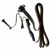
CABLE 1.27MM FOR RCM3200
Manufacturer
Rabbit Semiconductor
Datasheet
1.20-101-1217.pdf
(138 pages)
Specifications of 20-101-0542
Accessory Type
Programming Cable
Product
Microcontroller Accessories
For Use With/related Products
Rabbit 3000-based products, except RCM30/3100, LP3500
Lead Free Status / RoHS Status
Lead free / RoHS Compliant
Other names
20-101-0542
316-1180
316-1180


B.4 Using the Prototyping Board
The Prototyping Board is actually both a demonstration board and a prototyping board. As
a demonstration board, it can be used to demonstrate the functionality of the RCM3200
right out of the box without any modifications to either board. There are no jumpers or dip
switches to configure or misconfigure on the Prototyping Board so that the initial setup is
very straightforward.
The Prototyping Board comes with the basic components necessary to demonstrate the
operation of the RCM3200. Two LEDs (DS1 and DS2) are connected to PG6 and PG7,
and two switches (S2 and S3) are connected to PG1 and PG0 to demonstrate the interface
to the Rabbit 3000 microprocessor. Reset switch S1 is the hardware reset for the
RCM3200.
The Prototyping Board provides the user with RCM3200 connection points brought out con-
veniently to labeled points at headers J2 and J4 on the Prototyping Board. Small to medium
circuits can be prototyped using point-to-point wiring with 20 to 30 AWG wire between the
prototyping area and the holes at locations J2 and J4. The holes are spaced at 0.1" (2.5 mm),
and 40-pin headers or sockets may be installed at J2 and J4. The pinouts for locations J2 and
J4, which correspond to headers J1 and J2, are shown in Figure B-4.
Figure B-4. Prototyping Board Pinout
(Top View)
The small holes are also provided for surface-mounted components that may be installed
around the prototyping area.
There is a 2.0" × 3.5" through-hole prototyping space available on the Prototyping Board.
+3.3 V, +5 V, and GND traces run along the edge of the Prototyping Board for easy access.
User’s Manual
77
Related parts for 20-101-0542
Image
Part Number
Description
Manufacturer
Datasheet
Request
R

Part Number:
Description:
COMPUTER SGL-BRD BL2500 29.4MHZ
Manufacturer:
Rabbit Semiconductor
Datasheet:

Part Number:
Description:
COMPUTER SGL-BRD BL2500 29.4MHZ
Manufacturer:
Rabbit Semiconductor
Datasheet:

Part Number:
Description:
DISPLAY GRAPHIC 12KEY PROG OP670
Manufacturer:
Rabbit Semiconductor
Datasheet:
Part Number:
Description:
DISPLAY GRAPHIC 12KEY ETH OP6700
Manufacturer:
Rabbit Semiconductor
Datasheet:

Part Number:
Description:
COMPUTER SINGLE-BOARD BL2030
Manufacturer:
Rabbit Semiconductor
Part Number:
Description:
COMPUTER SGL-BOARD ETH BL2010
Manufacturer:
Rabbit Semiconductor

Part Number:
Description:
MODULE OP6810 W/O ETH/MEM EXPANS
Manufacturer:
Rabbit Semiconductor
Datasheet:
Part Number:
Description:
COMPUTER SINGLE-BOARD BL2020
Manufacturer:
Rabbit Semiconductor
Part Number:
Description:
COMPUTER BL2010 W/FRICTION LOCK
Manufacturer:
Rabbit Semiconductor
Part Number:
Description:
COMPUTER BL2020 W/FRICTION LOCK
Manufacturer:
Rabbit Semiconductor
Part Number:
Description:
COMPUTER SGL-BRD BL2500 44.2MHZ
Manufacturer:
Rabbit Semiconductor
Datasheet:
Part Number:
Description:
COMPUTER SGL-BOARD FULL BL2000
Manufacturer:
Rabbit Semiconductor

Part Number:
Description:
COMPUTER SINGLE-BOARD BL2110
Manufacturer:
Rabbit Semiconductor

Part Number:
Description:
COMPUTER SGL-BRD 29.4MHZ BL2610
Manufacturer:
Rabbit Semiconductor
Datasheet:
Part Number:
Description:
INTERFACE OP6800 512K FLASH&SRAM
Manufacturer:
Rabbit Semiconductor
Datasheet: