20-101-0542 Rabbit Semiconductor, 20-101-0542 Datasheet - Page 17
20-101-0542
Manufacturer Part Number
20-101-0542
Description
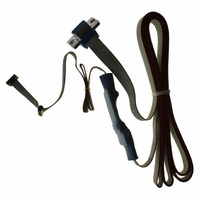
CABLE 1.27MM FOR RCM3200
Manufacturer
Rabbit Semiconductor
Datasheet
1.20-101-1217.pdf
(138 pages)
Specifications of 20-101-0542
Accessory Type
Programming Cable
Product
Microcontroller Accessories
For Use With/related Products
Rabbit 3000-based products, except RCM30/3100, LP3500
Lead Free Status / RoHS Status
Lead free / RoHS Compliant
Other names
20-101-0542
316-1180
316-1180


2.2.1 Step 1 — Attach Module to Prototyping Board
Turn the RCM3200 series module so that the Ethernet jack extends off the Prototyping
Board, as shown in Figure 2 below. Align the pins from the headers on the bottom side of
the module into header sockets RCM2JA and RCM2JB on the Prototyping Board (these
sockets were labeled J12 and J13 on earlier versions of the Prototyping Board).
Although you can install a single module into either the
on the Prototyping Board, all the Prototyping Board features (switches, LEDs, serial port
drivers, etc.) are connected to the
MASTER
Press the module’s pins firmly into the Prototyping Board header sockets—press down in
the area above the header pins using your thumbs or fingers over the connectors as shown
in Figure 2. Do not press down on the middle of the RCM3200 series module to avoid
flexing the module, which could damage the module or the components on the module.
Should you need to remove the RCM3200 module, grasp it with your fingers along the sides
by the connectors and gently work the module up to pull the pins away from the sockets
where they are installed. Do not remove the module by grasping it at the top and bottom.
User’s Manual
NOTE: It is important that you line up the pins from the headers on the bottom side of the
Figure 2. Install the RCM3200 Series Module on the Prototyping Board
RCM3200 module exactly with the corresponding pins of header sockets RCM2JA and
RCM2JB on the Prototyping Board. The header pins may become bent or damaged if
the pin alignment is offset, and the module will not work. Permanent electrical damage
to the module may also result if a misaligned module is powered up.
position.
MASTER
position — install a single module in the
MASTER
or the
SLAVE position
11
Related parts for 20-101-0542
Image
Part Number
Description
Manufacturer
Datasheet
Request
R

Part Number:
Description:
COMPUTER SGL-BRD BL2500 29.4MHZ
Manufacturer:
Rabbit Semiconductor
Datasheet:

Part Number:
Description:
COMPUTER SGL-BRD BL2500 29.4MHZ
Manufacturer:
Rabbit Semiconductor
Datasheet:

Part Number:
Description:
DISPLAY GRAPHIC 12KEY PROG OP670
Manufacturer:
Rabbit Semiconductor
Datasheet:
Part Number:
Description:
DISPLAY GRAPHIC 12KEY ETH OP6700
Manufacturer:
Rabbit Semiconductor
Datasheet:

Part Number:
Description:
COMPUTER SINGLE-BOARD BL2030
Manufacturer:
Rabbit Semiconductor
Part Number:
Description:
COMPUTER SGL-BOARD ETH BL2010
Manufacturer:
Rabbit Semiconductor

Part Number:
Description:
MODULE OP6810 W/O ETH/MEM EXPANS
Manufacturer:
Rabbit Semiconductor
Datasheet:
Part Number:
Description:
COMPUTER SINGLE-BOARD BL2020
Manufacturer:
Rabbit Semiconductor
Part Number:
Description:
COMPUTER BL2010 W/FRICTION LOCK
Manufacturer:
Rabbit Semiconductor
Part Number:
Description:
COMPUTER BL2020 W/FRICTION LOCK
Manufacturer:
Rabbit Semiconductor
Part Number:
Description:
COMPUTER SGL-BRD BL2500 44.2MHZ
Manufacturer:
Rabbit Semiconductor
Datasheet:
Part Number:
Description:
COMPUTER SGL-BOARD FULL BL2000
Manufacturer:
Rabbit Semiconductor

Part Number:
Description:
COMPUTER SINGLE-BOARD BL2110
Manufacturer:
Rabbit Semiconductor

Part Number:
Description:
COMPUTER SGL-BRD 29.4MHZ BL2610
Manufacturer:
Rabbit Semiconductor
Datasheet:
Part Number:
Description:
INTERFACE OP6800 512K FLASH&SRAM
Manufacturer:
Rabbit Semiconductor
Datasheet: