20-101-0542 Rabbit Semiconductor, 20-101-0542 Datasheet - Page 79
20-101-0542
Manufacturer Part Number
20-101-0542
Description
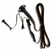
CABLE 1.27MM FOR RCM3200
Manufacturer
Rabbit Semiconductor
Datasheet
1.20-101-1217.pdf
(138 pages)
Specifications of 20-101-0542
Accessory Type
Programming Cable
Product
Microcontroller Accessories
For Use With/related Products
Rabbit 3000-based products, except RCM30/3100, LP3500
Lead Free Status / RoHS Status
Lead free / RoHS Compliant
Other names
20-101-0542
316-1180
316-1180


B.1.1 Prototyping Board Features
•
•
•
•
•
•
•
•
•
User’s Manual
Power Connection
nection to the power supply. Note that the 3-pin header is symmetrical, with both outer
pins connected to ground and the center pin connected to the raw V+ input. The cable
of the AC adapter provided with the North American version of the Development Kit
ends in a plug that connects to the power-supply jack. The header plug leading to bare
leads provided for overseas customers can be connected to the 3-pin header in either
orientation.
Users providing their own power supply should ensure that it delivers 8–24 V DC at
8 W. The voltage regulators will get warm while in use.
Regulated Power Supply
routed to a 5 V switching voltage regulator, then to a separate 3.3 V linear regulator.
The regulators provide stable power to the RCM3200 module and the Prototyping
Board.
Power LED
Board.
Reset Switch
RCM3200’s
I/O Switches and LEDs
nected to the PG0 and PG1 pins of the master RCM3200 module and may be read as
inputs by sample applications.
Two LEDs are connected to the PG6 and PG7 pins of the master module, and may be
driven as output indicators by sample applications.
Prototyping Area
of through-hole components. +3.3 V, +5 V, and Ground buses run around the edge of
this area. Several areas for surface-mount devices are also available. (Note that there
are SMT device pads on both top and bottom of the Prototyping Board.) Each SMT pad
is connected to a hole designed to accept a 30 AWG solid wire.
Master Module Connectors
of the first RCM3000, RCM3100, or RCM3200 module that serves as the primary or
“master module.”
Slave Module Connectors
lation of a second, slave RCM3200, RCM3100, or RCM3000 module. This capability
is reserved for future use, although the schematics in this manual contain all of the
details an experienced developer will need to implement a master-slave system.
Module Extension Headers
SLAVE
can solder wires directly into the appropriate holes, or, for more flexible development,
26-pin header strips can be soldered into place. See Figure B-4 for the header pinouts.
RabbitCore modules are duplicated at these two sets of headers. Developers
—The power LED lights whenever power is connected to the Prototyping
/RESET_IN
—A momentary-contact, normally open switch is connected directly to the
—A generous prototyping area has been provided for the installation
—A power-supply jack and a 3-pin header are provided for con-
pin. Pressing the switch forces a hardware reset of the system.
—Two momentary-contact, normally open switches are con-
—The raw DC voltage provided at the POWER IN jack is
—A second set of connectors is pre-wired to permit instal-
—The complete pin sets of both the
—A set of connectors is pre-wired to permit installation
MASTER
and
73
Related parts for 20-101-0542
Image
Part Number
Description
Manufacturer
Datasheet
Request
R

Part Number:
Description:
COMPUTER SGL-BRD BL2500 29.4MHZ
Manufacturer:
Rabbit Semiconductor
Datasheet:

Part Number:
Description:
COMPUTER SGL-BRD BL2500 29.4MHZ
Manufacturer:
Rabbit Semiconductor
Datasheet:

Part Number:
Description:
DISPLAY GRAPHIC 12KEY PROG OP670
Manufacturer:
Rabbit Semiconductor
Datasheet:
Part Number:
Description:
DISPLAY GRAPHIC 12KEY ETH OP6700
Manufacturer:
Rabbit Semiconductor
Datasheet:

Part Number:
Description:
COMPUTER SINGLE-BOARD BL2030
Manufacturer:
Rabbit Semiconductor
Part Number:
Description:
COMPUTER SGL-BOARD ETH BL2010
Manufacturer:
Rabbit Semiconductor

Part Number:
Description:
MODULE OP6810 W/O ETH/MEM EXPANS
Manufacturer:
Rabbit Semiconductor
Datasheet:
Part Number:
Description:
COMPUTER SINGLE-BOARD BL2020
Manufacturer:
Rabbit Semiconductor
Part Number:
Description:
COMPUTER BL2010 W/FRICTION LOCK
Manufacturer:
Rabbit Semiconductor
Part Number:
Description:
COMPUTER BL2020 W/FRICTION LOCK
Manufacturer:
Rabbit Semiconductor
Part Number:
Description:
COMPUTER SGL-BRD BL2500 44.2MHZ
Manufacturer:
Rabbit Semiconductor
Datasheet:
Part Number:
Description:
COMPUTER SGL-BOARD FULL BL2000
Manufacturer:
Rabbit Semiconductor

Part Number:
Description:
COMPUTER SINGLE-BOARD BL2110
Manufacturer:
Rabbit Semiconductor

Part Number:
Description:
COMPUTER SGL-BRD 29.4MHZ BL2610
Manufacturer:
Rabbit Semiconductor
Datasheet:
Part Number:
Description:
INTERFACE OP6800 512K FLASH&SRAM
Manufacturer:
Rabbit Semiconductor
Datasheet: