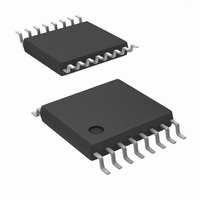
LM5115MTC/NOPB National Semiconductor, LM5115MTC/NOPB Datasheet - Page 14

LM5115MTC/NOPB
Manufacturer Part Number
LM5115MTC/NOPB
Description
IC CTRLR SSPR MULT OUTPT 16TSSOP
Manufacturer
National Semiconductor
Type
Step-Down (Buck)r
Datasheet
1.LM5115SDNOPB.pdf
(17 pages)
Specifications of LM5115MTC/NOPB
Internal Switch(s)
No
Synchronous Rectifier
Yes
Number Of Outputs
2
Voltage - Output
0.7 ~ 13.5 V
Current - Output
20A
Frequency - Switching
1MHz
Voltage - Input
4.5 ~ 75 V
Operating Temperature
-40°C ~ 125°C
Mounting Type
Surface Mount
Package / Case
16-TSSOP
Power - Output
300W
For Use With
LM5115EVAL - BOARD EVALUATION LM5115LM5115DC EVAL - BOARD EVALUATION LM5115DCLM5115AEVAL - BOARD EVALUATION LM5115A
Lead Free Status / RoHS Status
Lead free / RoHS Compliant
Other names
*LM5115MTC
*LM5115MTC/NOPB
LM5115MTC
*LM5115MTC/NOPB
LM5115MTC
Available stocks
Company
Part Number
Manufacturer
Quantity
Price
Part Number:
LM5115MTC/NOPB
Manufacturer:
NS/国半
Quantity:
20 000
www.national.com
Gate Drivers Outputs (HO & LO)
side MOSFET. The high side pulse is terminated when the
phase signal falls and SYNC input comparator resets the
PWM latch.
Thermal Protection
Internal thermal shutdown circuitry is provided to protect the
integrated circuit in the event the maximum junction tem-
perature limit is exceeded. When activated, typically at 165
degrees Celsius, the controller is forced into a low power
standby state with the output drivers and the bias regulator
disabled. The device will restart when the junction tempera-
ture falls below the thermal shutdown hysteresis, which is
typically 25 degrees. The thermal protection feature is pro-
vided to prevent catastrophic failures from accidental device
overheating.
Standalone DC/DC Synchronous
Buck Mode
The LM5115 can be configured as a standalone DC/DC
synchronous buck controller. In this mode the LM5115 uses
(Continued)
FIGURE 8. Simplified Typical Application Circuit (Synchronous Buck Mode)
FIGURE 9. Efficiency vs. Load Current and V
14
leading edge modulation in conjunction with valley current
mode control to control the synchronous buck power stage.
The internal oscillator within the LM5115 sets the clock
frequency for the high and low side drivers of the external
synchronous buck power MOSFETs . The clock frequency in
the synchronous buck mode is programmed by the SYNC
pin resistor and RAMP pin capacitor. Connecting a resistor
between a dc bias supply and the SYNC pin produces a
current, I
pin capacitor . The RAMP capacitor is charged until its
voltage reaches the peak ramp threshold of 2.25V. The
RAMP capacitor is then discharged for 300ns before begin-
ning a new PWM cycle. The 300ns reset time of the RAMP
pin sets the minimum off time of the PWM controller in this
mode. The internal clock frequency in the synchronous buck
mode is set by I
threshold, and the 300ns deadtime.
See the LM5115 dc evaluation board application note (AN-
1367) for more details on the synchronous buck mode.
F
IN
CLK
(Synchronous Buck Mode)
SYNC
) 1 / ((C
20134924
, which sets the charging current of the RAMP
SYNC
RAMP
, the ramp capacitor, the peak ramp
x 2.25V) / (I
20134923
SYNC
x 3) + 300ns)


