X9530V14I Intersil, X9530V14I Datasheet - Page 3
X9530V14I
Manufacturer Part Number
X9530V14I
Description
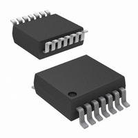
IC LASR CTRLR 1CHAN 5.5V 14TSSOP
Manufacturer
Intersil
Type
Laser Diode Controller (Fiber Optic)r
Datasheet
1.X9530V14IZT1.pdf
(28 pages)
Specifications of X9530V14I
Number Of Channels
1
Voltage - Supply
3 V ~ 5.5 V
Current - Supply
9mA
Operating Temperature
-40°C ~ 100°C
Package / Case
14-TSSOP
Mounting Type
Surface Mount
Lead Free Status / RoHS Status
Contains lead / RoHS non-compliant
Available stocks
Company
Part Number
Manufacturer
Quantity
Price
Company:

Part Number:
X9530V14I
Manufacturer:
Intersil
Quantity:
270


The general purpose memory portion of the device is a
CMOS serial EEPROM array with Intersil’s Block
Lock
fiber optic module manufacturing data, serial numbers,
or various other system parameters.
PIN ASSIGNMENTS
TSSOP
Pin
10
11
12
13
14
TM
1
2
3
4
5
6
7
8
9
protection. This memory may be used to store
VSense
Name
VRef
SDA
SCL
Pin
Vcc
WP
Vss
A0
A1
A2
R1
R2
I2
I1
Device Address Select Pin 0. This pin determines the LSB of the device address
required to communicate using the 2-wire interface. The A0 pin has an on-chip pull-down resistor.
Device Address Select Pin 1. This pin determines the intermediate bit of the device address re-
quired to communicate using the 2-wire interface. The A1 pin has an on-chip pull-down resistor.
Device Address Select Pin 2. This pin determines the MSB of the device address required to
communicate using the 2-wire interface. The A2 pin has an on-chip pull-down resistor.
Supply Voltage.
Write Protect Control Pin. This pin is a CMOS compatible input. When LOW, Write Protection
is enabled preventing any “Write” operation. When HIGH, various areas of the memory can be
protected using the Block Lock bits BL1 and BL0. The WP pin has an on-chip pull-down resistor,
which enables the Write Protection when this pin is left floating.
Serial Clock. This is a TTL compatible input pin. This input is the 2-wire interface clock controlling
data input and output at the SDA pin.
Serial Data. This pin is the 2-wire interface data into or out of the device. It is TTL
compatible when used as an input, and it is Open Drain when used as an output. This pin requires
an external pull up resistor.
Current Generator 1 Output. This pin sinks or sources current. The magnitude and direction of
the current is fully programmable and adaptive. The resolution is 8 bits.
Current Programming Resistor 1. A resistor between this pin and Vss can set the maximum
output current available at pin I1. If no resistor is used, the maximum current must be selected
using control register bits.
Current Programming Resistor 2. A resistor between this pin and Vss can set the maximum
output current available at pin I2. If no resistor is used, the maximum current must be selected
using control register bits.
Ground.
Sensor Voltage Input. This voltage input may be used to drive the input of the on-chip A/D con-
verter.
Reference Voltage Input or Output. This pin can be configured as either an Input or an Output.
As an Input, the voltage at this pin is provided by an external source. As an Output, the voltage
at this pin is a buffered output voltage of the on-chip bandgap reference circuit. In both cases, the
voltage at this pin is the reference for the A/D
converter and the two D/A converters.
Current Generator 2 Output. This pin sinks or sources current. The magnitude and direction of
the current is fully programmable and adaptive. The resolution is 8 bits.
3
X9530
Pin Description
The EEPROM array is internally organized as 272 x 8
bits with 16-Byte pages, and utilizes Intersil’s
proprietary Direct Write™ cells, providing a minimum
endurance of 100,000 Page Write cycles and a
minimum data retention of 100 years.
November 11, 2005
FN8211.1
Related parts for X9530V14I
Image
Part Number
Description
Manufacturer
Datasheet
Request
R

Part Number:
Description:
Temperature Compensated Laser Diode Controller
Manufacturer:
INTERSIL [Intersil Corporation]
Datasheet:

Part Number:
Description:
Temperature Compensated Laser Diode Controller
Manufacturer:
Intersil Corporation
Datasheet:
Part Number:
Description:
Intersil Corporation [CMOS Serial Controller Interface]
Manufacturer:
Intersil Corporation
Datasheet:
Part Number:
Description:
Manufacturer:
Intersil Corporation
Datasheet:
Part Number:
Description:
357-036-542-201 CARDEDGE 36POS DL .156 BLK LOPRO
Manufacturer:
Intersil Corporation
Datasheet:
Part Number:
Description:
1024-Word x 4-Bit LSI Static RAM
Manufacturer:
Intersil Corporation
Datasheet:
Part Number:
Description:
General Purpose NPN Transistor Arrays FN341.4
Manufacturer:
Intersil Corporation
Datasheet:
Part Number:
Description:
CMOS 16-Bit Microprocessor
Manufacturer:
Intersil Corporation
Datasheet:
Part Number:
Description:
Manufacturer:
Intersil Corporation
Datasheet:
Part Number:
Description:
Manufacturer:
Intersil Corporation
Datasheet:
Part Number:
Description:
Manufacturer:
Intersil Corporation
Datasheet:
Part Number:
Description:
Manufacturer:
Intersil Corporation
Datasheet:
Part Number:
Description:
CMOS 6-Bit Latch and Decoder Memory Interfaces
Manufacturer:
Intersil Corporation
Datasheet:
Part Number:
Description:
CA3046General Purpose NPN Transistor Arrays
Manufacturer:
Intersil Corporation
Datasheet:
Part Number:
Description:
Manufacturer:
Intersil Corporation
Datasheet: