X9530V14I Intersil, X9530V14I Datasheet - Page 25
X9530V14I
Manufacturer Part Number
X9530V14I
Description
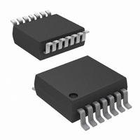
IC LASR CTRLR 1CHAN 5.5V 14TSSOP
Manufacturer
Intersil
Type
Laser Diode Controller (Fiber Optic)r
Datasheet
1.X9530V14IZT1.pdf
(28 pages)
Specifications of X9530V14I
Number Of Channels
1
Voltage - Supply
3 V ~ 5.5 V
Current - Supply
9mA
Operating Temperature
-40°C ~ 100°C
Package / Case
14-TSSOP
Mounting Type
Surface Mount
Lead Free Status / RoHS Status
Contains lead / RoHS non-compliant
Available stocks
Company
Part Number
Manufacturer
Quantity
Price
Company:

Part Number:
X9530V14I
Manufacturer:
Intersil
Quantity:
270


A/D CONVERTER CHARACTERISTICS
All typical values are for 25°C ambient temperature and 5 V at pin Vcc. Maximum and minimum specifications are over the
recommended operating conditions. All voltages are referred to the voltage at pin Vss unless otherwise specified. All bits in control
registers are “0” unless otherwise specified.
unless otherwise specified. 400kHz TTL input at SCL unless otherwise specified. SDA pulled to Vcc through an external 2kΩ resistor
unless otherwise specified. 2-wire interface in “standby” (see notes 1 and 2 on page 22), unless otherwise specified. WP, A0, A1, and A2
floating unless otherwise specified.
Notes: 1. “LSB” is defined as V(VRef)/63, “Full Scale” is defined as V(VRef).
ADCTIME
RIN
CIN
VIN
Offset
FSError
DNL
INL
TempStep
Out25
Symbol
ADC
ADC
ADC
ADC
ADC
2. Offset
3. These parameters are periodically sampled and not 100% tested.
ADC
ADC
ADC
amount of deviation between the measured first transition point and the ideal point.
of deviation between the measured last transition point and the ideal point,
after subtracting the Offset from the measured curve.
expressed in LSBs. The measured transfer curve is adjusted for Offset and Fullscale errors before calculating DNL.
defined as the sum of the DNL errors starting from code 00h to the code where the INL measurement is desired. The measured trans-
fer curve is adjusted for Offset and Fullscale errors before calculating INL.
FSError
DNL
INL
ADC
ADC
ADC
ADC
: The deviation of the measured transfer function of an A/D converter from the ideal transfer function. The INL error is also
ADC
: DNL is defined as the difference between the ideal and the measured code transitions for successive A/D code outputs
: For an ideal converter, the first transition of its transfer curve occurs a
A/D converter conversion
time
VSense pin input
resistance
VSense pin input
capacitance
VSense input signal range
A/D converter offset error
A/D converter full scale er-
ror
A/D Converter Differential
Nonlinearity
A/D converter Integral
Nonlinearity
Temperature step causing
one step increment of ADC
output
ADC output at 25°C
: For an ideal converter, the last transition of its transfer curve occurs at
Parameter
25
510Ω, 0.1%,
-0.25
Min
-0.5
-0.5
100
2.1
-1
1
0
resistor connected between R1 and Vss, and another between R2 and Vss
X9530
011101
Typ
2.2
2
V(VRef)
Max
0.25
0.5
0.5
2.3
9
7
1
Unit
LSB
LSB
LSB
LSB
[
ms
k
pF
°C
[
V
251
Ω
3
1
/
2
1
/
x V(VRef)
2
255
255
x V(VRef)
Proportional to A/D converter
input voltage. This value is
maximum at full scale input
of A/D converter.
ADCfiltOff = “1”
VSense as an input,
ADCIN bit = “1”
VSense as an input,
ADCIN bit = “1”,
Frequency = 1 MHz
See note 3.
This is the A/D Converter
Dynamic Range. ADCIN bit = “1”
See notes 1 and 2
Test Conditions / Notes
]
]
above zero. Offset error is the
.Full Scale Error is the amount
November 11, 2005
FN8211.1
Related parts for X9530V14I
Image
Part Number
Description
Manufacturer
Datasheet
Request
R

Part Number:
Description:
Temperature Compensated Laser Diode Controller
Manufacturer:
INTERSIL [Intersil Corporation]
Datasheet:

Part Number:
Description:
Temperature Compensated Laser Diode Controller
Manufacturer:
Intersil Corporation
Datasheet:
Part Number:
Description:
Intersil Corporation [CMOS Serial Controller Interface]
Manufacturer:
Intersil Corporation
Datasheet:
Part Number:
Description:
Manufacturer:
Intersil Corporation
Datasheet:
Part Number:
Description:
357-036-542-201 CARDEDGE 36POS DL .156 BLK LOPRO
Manufacturer:
Intersil Corporation
Datasheet:
Part Number:
Description:
1024-Word x 4-Bit LSI Static RAM
Manufacturer:
Intersil Corporation
Datasheet:
Part Number:
Description:
General Purpose NPN Transistor Arrays FN341.4
Manufacturer:
Intersil Corporation
Datasheet:
Part Number:
Description:
CMOS 16-Bit Microprocessor
Manufacturer:
Intersil Corporation
Datasheet:
Part Number:
Description:
Manufacturer:
Intersil Corporation
Datasheet:
Part Number:
Description:
Manufacturer:
Intersil Corporation
Datasheet:
Part Number:
Description:
Manufacturer:
Intersil Corporation
Datasheet:
Part Number:
Description:
Manufacturer:
Intersil Corporation
Datasheet:
Part Number:
Description:
CMOS 6-Bit Latch and Decoder Memory Interfaces
Manufacturer:
Intersil Corporation
Datasheet:
Part Number:
Description:
CA3046General Purpose NPN Transistor Arrays
Manufacturer:
Intersil Corporation
Datasheet:
Part Number:
Description:
Manufacturer:
Intersil Corporation
Datasheet: