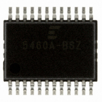
CS5460A-BSZ Cirrus Logic Inc, CS5460A-BSZ Datasheet - Page 44

CS5460A-BSZ
Manufacturer Part Number
CS5460A-BSZ
Description
IC ENERGY METERING 1PHASE 24SSOP
Manufacturer
Cirrus Logic Inc
Datasheet
1.CS5460A-BSZ.pdf
(54 pages)
Specifications of CS5460A-BSZ
Package / Case
24-SSOP
Input Impedance
30 KOhm
Measurement Error
0.1%
Voltage - I/o High
0.8V
Voltage - I/o Low
0.2V
Current - Supply
2.9mA
Voltage - Supply
4.75 V ~ 5.25 V
Operating Temperature
-40°C ~ 85°C
Mounting Type
Surface Mount
Meter Type
Single Phase
Output Voltage Range
2.4 V to 2.6 V
Output Current
1 uA
Input Voltage Range
2.4 V to 2.6 V
Input Current
25 nA
Power Dissipation
500 mW
Operating Temperature Range
- 40 C to + 85 C
Mounting Style
SMD/SMT
Ic Function
Single Phase Bi-directional Power / Energy IC
Brief Features
On-Chip Functions, AC Or DC System Calibration, Power Supply Monitor
Supply Voltage Range
3.3V To 5V
Rohs Compliant
Yes
Lead Free Status / RoHS Status
Lead free / RoHS Compliant
For Use With
CDB5460AU - EVALUATION BOARD FOR CS5460A
Lead Free Status / Rohs Status
Lead free / RoHS Compliant
Other names
598-1094-5
Available stocks
Company
Part Number
Manufacturer
Quantity
Price
Company:
Part Number:
CS5460A-BSZ
Manufacturer:
CIRRUS
Quantity:
2
Company:
Part Number:
CS5460A-BSZR
Manufacturer:
CIRRUS
Quantity:
8 000
Part Number:
CS5460A-BSZR
Manufacturer:
CIRRUS
Quantity:
20 000
5. REGISTER DESCRIPTIONS
Note:
5.1 Configuration Register
44
Current
Channel
Voltage
Channel
Address: 0
Default** = 0x000001
K[3:0]
iCPU
IHPF
VHPF
EWA
PC6
RS
23
15
7
1.
2. Note that all registers can be read from, and written to.
Timebase Cal. Register (1 x 24)
Power Offset Register (1 x 24)
AC Offset Register (1 x 24)
AC Offset Register (1 x 24)
** “default” => bit status after software or hardware reset
VHPF
PC5
Res
22
14
clock DCLK. The internal clock frequency is DCLK = MCLK/K. The value of K can range be-
tween 1 and 16. Note that a value of “0000” will set K to 16 (not zero).
are sampled, the logic driven by CPUCLK should not be active during the sample edge.
0 = normal operation (default)
1 = minimize noise when CPUCLK is driving rising edge logic
0 = High-pass filter is disabled. If VHPF is set, use all-pass filter. Otherwise, no filter is used.
(default)
1 = High-pass filter is enabled.
0 = High-pass filter is disabled. If IHPF is set, use all-pass filter. Otherwise, no filter is used.
(default)
1 = High-pass filter enabled
Clock divider. A 4 bit binary number used to divide the value of MCLK to generate the internal
Inverts the CPUCLK clock. In order to reduce the level of noise present when analog signals
Control the use of the High Pass Filter on the Current Channel.
Control the use of the High Pass Filter on the voltage Channel.
6
Configuration Register (1 × 24)
Pulse-Rat e Register (1 × 24)
IHPF
DC
DC
PC4
Res
Control Register (1 x 24)
21
13
5
Offset Register (1 × 24)
Offset Register (1 × 24)
Figure 21. CS5460A Register Diagram
iCPU
PC3
SI1
20
12
4
Cycle-Counter Registe
AC/DC
AC/DC
Status Register (1 × 24)
Mask Register (1 × 24)
Gain Register (1 × 24)
Gain Register (1 × 24)
PC2
SI0
K3
19
11
3
r (1 × 24)
EOD
PC1
18
10
K2
2
24-Bit
Signed Output Registers (4 × 24)
(I, V, P, E)
Unsigned Output Registers (2 × 24)
(I
RMS
, V
RMS
PC0
DL1
K1
17
Command Word
9
1
Transmit Buffer
State Machine
Serial Interface
Receive Buffer
)
CS5460A
DS487F4
DL0
16
K0
Gi
8
0
SCLK
SDI
CS
SDO
INT


