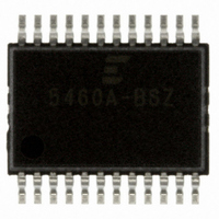
CS5460A-BSZ Cirrus Logic Inc, CS5460A-BSZ Datasheet - Page 24

CS5460A-BSZ
Manufacturer Part Number
CS5460A-BSZ
Description
IC ENERGY METERING 1PHASE 24SSOP
Manufacturer
Cirrus Logic Inc
Datasheet
1.CS5460A-BSZ.pdf
(54 pages)
Specifications of CS5460A-BSZ
Package / Case
24-SSOP
Input Impedance
30 KOhm
Measurement Error
0.1%
Voltage - I/o High
0.8V
Voltage - I/o Low
0.2V
Current - Supply
2.9mA
Voltage - Supply
4.75 V ~ 5.25 V
Operating Temperature
-40°C ~ 85°C
Mounting Type
Surface Mount
Meter Type
Single Phase
Output Voltage Range
2.4 V to 2.6 V
Output Current
1 uA
Input Voltage Range
2.4 V to 2.6 V
Input Current
25 nA
Power Dissipation
500 mW
Operating Temperature Range
- 40 C to + 85 C
Mounting Style
SMD/SMT
Ic Function
Single Phase Bi-directional Power / Energy IC
Brief Features
On-Chip Functions, AC Or DC System Calibration, Power Supply Monitor
Supply Voltage Range
3.3V To 5V
Rohs Compliant
Yes
Lead Free Status / RoHS Status
Lead free / RoHS Compliant
For Use With
CDB5460AU - EVALUATION BOARD FOR CS5460A
Lead Free Status / Rohs Status
Lead free / RoHS Compliant
Other names
598-1094-5
Available stocks
Company
Part Number
Manufacturer
Quantity
Price
Company:
Part Number:
CS5460A-BSZ
Manufacturer:
CIRRUS
Quantity:
2
Company:
Part Number:
CS5460A-BSZR
Manufacturer:
CIRRUS
Quantity:
8 000
Part Number:
CS5460A-BSZR
Manufacturer:
CIRRUS
Quantity:
20 000
pulse, one of the output pins (either EOUT or
EDIR) changes state. When the CS5460A must is-
sue another energy pulse, the other output chang-
es state. The direction the motor will rotate is
determined by the order of the state changes.
3.3 Auto-boot Mode Using EEPROM
The CS5460A has a MODE pin. When the MODE
pin is set to logic low, the CS5460A is in normal op-
erating mode, called host mode. This mode de-
notes the normal operation of the part, that has
been described so far. But when this pin is set to
logic high, the CS5460A auto-boot mode is en-
abled. In auto-boot mode, the CS5460A is config-
ured to request a memory download from an
external serial EEPROM. The download sequence
is initiated by driving the RESET pin to logic high.
Auto-boot mode allows the CS5460A to operate
without the need for a microcontroller. Note that if
the MODE pin is left unconnected, it will default to
logic low because of an internal pull-down on the
pin.
24
EOUT
EDIR
...
...
5 K
VD+
Figure 12. Stepper Motor Format on EOUT and EDIR
Figure 13. Typical Interface of EEPROM to CS5460A
MODE
CS5460A
Positive Energy
/EOUT
/EDIR
SDO
SCK
/CS
SDI
Connector to
Calibrator
When energy is positive, EOUT will lead EDIR
such that the EOUT pulse train will lead the EDIR
pulse train by ~1/4 of the periods of these two
pulse train signal. When energy is negative, EDIR
will lead EOUT in a similar manner. See Figure 12.
3.3.1 Auto-boot Configuration
Figure 13 shows the typical connections between
the CS5460A and a serial EEPROM for proper au-
to-boot operation. In this mode, CS and SCLK are
driven outputs. SDO is always an output. During
the auto-boot sequence, the CS5460A drives CS
low, provides a clock output on SCLK, and drives
out-commands on SDO. It receives the EEPROM
data on SDI. The serial EEPROM must be pro-
grammed with the user-specified commands and
register data that will be used by the CS5460A to
change any of the default register values (if de-
sired) and begin conversions.
Figure 13 also shows the external connections that
would be made to a calibrator device, such as a PC
Mech. Counter
Stepper Motor
5 K
or
Negative Energy
SCK
SI
SO
/CS
EEPROM
CS5460A
...
...
DS487F4


