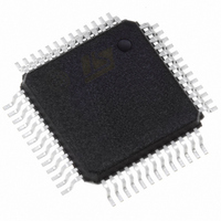
STFPC311BTR STMicroelectronics, STFPC311BTR Datasheet - Page 8

STFPC311BTR
Manufacturer Part Number
STFPC311BTR
Description
IC CTRL/DRIVER FRONT PNL 52-PQFP
Manufacturer
STMicroelectronics
Datasheet
1.STFPC311BTR.pdf
(39 pages)
Specifications of STFPC311BTR
Display Type
Vacuum Fluorescent (VF)
Interface
Serial
Current - Supply
5mA
Voltage - Supply
3 V ~ 33.3 V
Operating Temperature
-40°C ~ 85°C
Mounting Type
Surface Mount
Package / Case
52-MQFP, 52-PQFP
Maximum Operating Temperature
+ 85 C
Maximum Clock Frequency
1 MHz
Maximum Output Current
25 mA
Maximum Power Dissipation
1200 mA
Minimum Operating Temperature
- 40 C
Mounting Style
SMD/SMT
For Use With
497-8394 - BOARD DEMO STFPC311/ST72264497-6454 - BOARD EVAL BASED ON STFPC311
Lead Free Status / RoHS Status
Lead free / RoHS Compliant
Configuration
-
Digits Or Characters
-
Lead Free Status / Rohs Status
Details
Other names
497-6107-2
Available stocks
Company
Part Number
Manufacturer
Quantity
Price
Company:
Part Number:
STFPC311BTR
Manufacturer:
TI
Quantity:
200
Company:
Part Number:
STFPC311BTR
Manufacturer:
STMicroelectronics
Quantity:
10 000
Part Number:
STFPC311BTR
Manufacturer:
ST
Quantity:
20 000
3 Initialization
3.4
3.5
3.6
Note:
8/39
Standby or power-down mode
Once the STFPC311 detects the status change of the READY to a logic low or after the preset
waiting time (1s to 15s) has elapsed, the STFPC311 sets the STBY pin to a logic high to turn off
the power. The MUTE signal is set to high before the power is turned off. The STFPC311
always senses the level on the READY pin during normal operation.
IR Decoding
Encoded IR data from photodiode is supplied to the IR_DATA_IN input pin. The data is
decoded by the internal remote control decoder module of STFPC311. In standby mode, the
remote control decoder recognizes a set of predefined commands (such as STANDBY, PLAY,
and OPEN/CLOSE), and takes appropriate action to manage the power supply.
These predefined commands are known as "hot keys" and are programmable. The decoded IR
commands are passed on to the main processor through the SPI interface by sending 3 bytes
of data on the D
Watchdog timer
The watchdog timer is used to detect an out-of-control microprocessor. The watch dog timer is
implemented in the STFPC311 to detect the abnormal processor behavior or processor-hung
condition. The default state of the watchdog timer is 10s when the device powers-up. It is
initialized by writing to the watchdog register and can be programmed to up to 15s (4-bit
watchdog timer, present in the configuration mode setting command).
If the processor does not reset the timer within the specified period, the STFPC311 will put the
entire system into standby mode to reset the appliance that has stopped abnormally. The action
to take when the watchdog timer has reached its count is to set the Watchdog Action register.
The watchdog timer can be reset by the host processor by sending a command to reset the
watchdog timer. The time-out period then starts over again. If the processor needs to be reset
as a result of a hung condition (signalled using the STBY output of the STFPC311), the
watchdog timer uses the amount of the time-out programmed into the Watchdog Register by
the user to generate an interrupt.
The accuracy of the timer is within ±10% the selected resolution. This depends on the value of
the external bias resistor, as it determines the internal clock frequency.
The watchdog function is automatically set to 10s upon power-up and the Watchdog Interrupt is
cleared. This boot-up watchdog timer is used to make sure that if the host processor hangs
during the first boot-up, the STFPC311 will put the system to standby mode. During the first
boot-up, the watchdog timer is disabled after the first READY signal is received.
OUT
pin.
STFPC311


