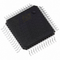
STFPC311BTR STMicroelectronics, STFPC311BTR Datasheet - Page 7

STFPC311BTR
Manufacturer Part Number
STFPC311BTR
Description
IC CTRL/DRIVER FRONT PNL 52-PQFP
Manufacturer
STMicroelectronics
Datasheet
1.STFPC311BTR.pdf
(39 pages)
Specifications of STFPC311BTR
Display Type
Vacuum Fluorescent (VF)
Interface
Serial
Current - Supply
5mA
Voltage - Supply
3 V ~ 33.3 V
Operating Temperature
-40°C ~ 85°C
Mounting Type
Surface Mount
Package / Case
52-MQFP, 52-PQFP
Maximum Operating Temperature
+ 85 C
Maximum Clock Frequency
1 MHz
Maximum Output Current
25 mA
Maximum Power Dissipation
1200 mA
Minimum Operating Temperature
- 40 C
Mounting Style
SMD/SMT
For Use With
497-8394 - BOARD DEMO STFPC311/ST72264497-6454 - BOARD EVAL BASED ON STFPC311
Lead Free Status / RoHS Status
Lead free / RoHS Compliant
Configuration
-
Digits Or Characters
-
Lead Free Status / Rohs Status
Details
Other names
497-6107-2
Available stocks
Company
Part Number
Manufacturer
Quantity
Price
Company:
Part Number:
STFPC311BTR
Manufacturer:
TI
Quantity:
200
Company:
Part Number:
STFPC311BTR
Manufacturer:
STMicroelectronics
Quantity:
10 000
Part Number:
STFPC311BTR
Manufacturer:
ST
Quantity:
20 000
STFPC311
3
3.1
3.2
3.3
Initialization
After the power is plugged in, the device will supply power to all of the components (including
the host processor) by setting STBY to logic low in order to allow the host processor to program
the STFPC311. Once the STBY is set to low, the watchdog timer starts to count up to 10s (10s
is the default value of the watchdog timer upon power-up). When the READY is asserted within
this time, it indicates that the system has booted up well. If the READY pin is not asserted (logic
high) within this time (10s), the STFPC311 will put the system into standby mode again by
setting STBY to logic high.
If READY is detected as logic high, the watchdog timer will be turned OFF. The main processor
should program the remote control hot key and initialize the other parameters of the STFPC311
in preparation for normal operation before the system goes into standby mode. After all of the
STFPC311 configuration is finished, the host processor may set the READY to low so that the
STFPC311 enters standby mode. The STFPC311 then sets the MUTE pin to logic high to mute
the audio output as well as the STBY pin to logic high. As a consequence of this action, the
main supply voltage is turned off.
Normal mode of operation
After the power is plugged in, the device will supply power to all of the components (including
the host processor) by setting STBY to logic low in order to allow the host processor to program
the STFPC311. Once the STBY is set to low, the watchdog timer starts to count up to 10s (10s
is the default value of the watchdog timer upon power-up). When the READY is asserted within
this time, it indicates that the system has booted up well. If the READY pin is not asserted (logic
high) within this time (10s), the STFPC311 will put the system into standby mode again by
setting STBY to logic high.
If READY is detected as logic high, the watchdog timer will be turned OFF. The main processor
should program the remote control hot key and initialize the other parameters of the STFPC311
in preparation for normal operation before the system goes into standby mode. After all of the
STFPC311 configuration is finished, the host processor may set the READY to low so that the
STFPC311 enters standby mode. The STFPC311 then sets the MUTE pin to logic high to mute
the audio output as well as the STBY pin to logic high. As a consequence of this action, the
main supply voltage is turned off.
Receive operation
In receive condition, the STFPC311 waits for a valid command from the MCU. The receive
circuit of STFPC311 receives 8 bit serial data, latches the data and then masks the inputs from
the MCU. Refer to
Transmit operation
In transmit condition, the STFPC311 sends the 8-bit serial data (LSB transmitted first)
whenever a key is pressed or IR data is received. STFPC311 transmits data on the falling edge
of CLK. Refer to
Figure 29 on page 32
Figure 28 on page 32
for transmit timing.
for receive timing.
3 Initialization
7/39


