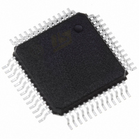
STFPC311BTR STMicroelectronics, STFPC311BTR Datasheet - Page 26

STFPC311BTR
Manufacturer Part Number
STFPC311BTR
Description
IC CTRL/DRIVER FRONT PNL 52-PQFP
Manufacturer
STMicroelectronics
Datasheet
1.STFPC311BTR.pdf
(39 pages)
Specifications of STFPC311BTR
Display Type
Vacuum Fluorescent (VF)
Interface
Serial
Current - Supply
5mA
Voltage - Supply
3 V ~ 33.3 V
Operating Temperature
-40°C ~ 85°C
Mounting Type
Surface Mount
Package / Case
52-MQFP, 52-PQFP
Maximum Operating Temperature
+ 85 C
Maximum Clock Frequency
1 MHz
Maximum Output Current
25 mA
Maximum Power Dissipation
1200 mA
Minimum Operating Temperature
- 40 C
Mounting Style
SMD/SMT
For Use With
497-8394 - BOARD DEMO STFPC311/ST72264497-6454 - BOARD EVAL BASED ON STFPC311
Lead Free Status / RoHS Status
Lead free / RoHS Compliant
Configuration
-
Digits Or Characters
-
Lead Free Status / Rohs Status
Details
Other names
497-6107-2
Available stocks
Company
Part Number
Manufacturer
Quantity
Price
Company:
Part Number:
STFPC311BTR
Manufacturer:
TI
Quantity:
200
Company:
Part Number:
STFPC311BTR
Manufacturer:
STMicroelectronics
Quantity:
10 000
Part Number:
STFPC311BTR
Manufacturer:
ST
Quantity:
20 000
9 Remote control protocols
9.2
9.3
26/39
SPI interface IR data transmission
The IR data is sent on the DOUT pin of the SPI interface when the micro controller issues a IR
data read command. The data is sent in 3 bytes with LSB transmitted first as shown in the
Figure below:
The RC data consists of RC address, start bit, toggle bit and the RC command received. The
extra bits are stuffed with 1’s to make it a 3-byte packet. These extra bits at the end of the
packet should be ignored.
Figure 24. RC-6 protocol frame
The RC data consists of RC address, start bit, toggle bit and the RC command received. The
extra bits are stuffed with 1’s to make it a 3-byte packet. These extra bits at the end of the
packet should be ignored.
NEC remote control
This remote control protocol uses pulse distance modulation. Each bit consists of a high level of
fixed time "t", followed by a low level that varies in width. A space that is "t" represents a logic '0'
and a space that is "3t" represents a logic '1'. t = 0.56ms.
The LSB is transmitted first as shown in
Figure 25. Pulse distance modulation.
Figure 25
STFPC311


