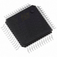
STFPC311BTR STMicroelectronics, STFPC311BTR Datasheet - Page 20

STFPC311BTR
Manufacturer Part Number
STFPC311BTR
Description
IC CTRL/DRIVER FRONT PNL 52-PQFP
Manufacturer
STMicroelectronics
Datasheet
1.STFPC311BTR.pdf
(39 pages)
Specifications of STFPC311BTR
Display Type
Vacuum Fluorescent (VF)
Interface
Serial
Current - Supply
5mA
Voltage - Supply
3 V ~ 33.3 V
Operating Temperature
-40°C ~ 85°C
Mounting Type
Surface Mount
Package / Case
52-MQFP, 52-PQFP
Maximum Operating Temperature
+ 85 C
Maximum Clock Frequency
1 MHz
Maximum Output Current
25 mA
Maximum Power Dissipation
1200 mA
Minimum Operating Temperature
- 40 C
Mounting Style
SMD/SMT
For Use With
497-8394 - BOARD DEMO STFPC311/ST72264497-6454 - BOARD EVAL BASED ON STFPC311
Lead Free Status / RoHS Status
Lead free / RoHS Compliant
Configuration
-
Digits Or Characters
-
Lead Free Status / Rohs Status
Details
Other names
497-6107-2
Available stocks
Company
Part Number
Manufacturer
Quantity
Price
Company:
Part Number:
STFPC311BTR
Manufacturer:
TI
Quantity:
200
Company:
Part Number:
STFPC311BTR
Manufacturer:
STMicroelectronics
Quantity:
10 000
Part Number:
STFPC311BTR
Manufacturer:
ST
Quantity:
20 000
6 Commands
6.3
6.4
Figure 17. STFPC311 Display control and hot key setting command order
20/39
When the application is powered-up, the normal operation mode and address increment mode
is set with the default display memory address set to 00H. In the auto-increment address mode,
the address command is sent once, followed by the data bytes.
Alternatively, the data command can be sent, followed by the data bytes. In this case, when new
display data is to be written, the last value of the address will be used and then incremented.
Upon reaching the last display memory address, the address jumps to 00H.
For fixed address mode, the address command has to be sent, followed by the display data.
When next byte of data is to be written, the address command has to be sent again before the
new display data byte.
For RC-5 data reception (after the photodiode), a binary 1 is represented by a high-to-low
transition, and a binary 0 is represented by a low-to-high transition. For RC-6 (Mode 0) data
reception, a binary 1 is represented by a low-to-high transition, and a binary 0 is represented by
a high-to-low transition. Whenever Bit 5 is a ‘1’, the watchdog timer is reset.
Address setting command
This command sets an address of the display memory. If address 30H or higher is set, the data
is ignored until a correct address is set.
Figure 16. STFPC311 Address Setting Command Order
Display control and hotkey setting command
When the application is powered-up, the 1/16-pulse width is set and the display is turned OFF.
See
Figure 17
and
Figure
4. All hot keys are disabled.
STFPC311


