MAX3140EEI+T Maxim Integrated Products, MAX3140EEI+T Datasheet - Page 27

MAX3140EEI+T
Manufacturer Part Number
MAX3140EEI+T
Description
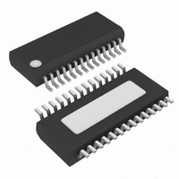
IC UART W/RS485 28-QSOP
Manufacturer
Maxim Integrated Products
Datasheet
1.MAX3140CEIT.pdf
(36 pages)
Specifications of MAX3140EEI+T
Features
Transceiver
Fifo's
8 Byte
Protocol
RS232, RS485
Voltage - Supply
4.75 V ~ 5.25 V
With Irda Encoder/decoder
Yes
With False Start Bit Detection
Yes
With Cmos
Yes
Mounting Type
Surface Mount
Package / Case
28-QSOP
Lead Free Status / RoHS Status
Lead free / RoHS Compliant
sis of a 20kHz signal transmitted with SRL = GND. High-
frequency harmonic components with large amplitudes
are evident. Figure 18 shows the same signal for SRL =
V
18’s high-frequency harmonic components are much
lower in amplitude, compared with Figure 17’s, and the
potential for EMI is significantly reduced. Figure 19
shows the same signal for SRL = unconnected, trans-
mitting under the same conditions. In general, a trans-
mitter’s rise time relates directly to the length of an
unterminated stub, which can be driven with only minor
waveform reflections, The following equation expresses
this relationship conservatively:
where t
For example, consider a rise time of 1320ns. This
results in excellent waveforms with a stub length up to
90 feet. A system can work well with longer unterminat-
ed stubs, even with severe reflections, if the waveform
settles out before the UART samples them.
Low-power shutdown mode is initiated by bringing both
RE high and DE low. RE and DE may be driven simulta-
neously; the MAX3140 is guaranteed not to enter shut-
down if RE is high and DE is low for less than 50ns. If
the inputs are in this state for at least 600ns, the device
is guaranteed to enter shutdown.
Figure 18. Driver Output Waveform and FFT Plot of MAX3140
with SRL = V
SPI/MICROWIRE-Compatible UART with Integrated
CC
, transmitting under the same conditions. Figure
20dB/div
RISE
Length = t
O
CC
is the transmitter’s rise time.
, Transmitting a 20kHz Signal
______________________________________________________________________________________
True Fail-Safe RS-485/RS-422 Transceivers
Low-Power Shutdown Mode
RISE
RS-485/RS-422 Transceiver
/ (10 · 1.5ns/ft)
100kHz/div
1MHz
A
Enable times t
acteristics tables assume the device was not in a low-
power shutdown state. Enable times t
t
drivers and receivers longer to become enabled from
low-power shutdown mode (t
from driver/receiver-disable mode (t
Two mechanisms prevent excessive output current and
power dissipation caused by faults or by bus con-
tention. The first, a foldback current limit on the output
stage, provides immediate protection against short cir-
cuits over the whole common-mode voltage range (see
Typical Operating Characteristics ). The second, a ther-
mal shutdown circuit, forces the driver outputs into a
high-impedance state if the die temperature becomes
excessive.
The RS-485/RS-422 standard covers line lengths up to
4000 feet. For line lengths greater than 4000 feet, use
the repeater application shown in Figure 20.
Figures 21, 22, and 23 show the system differential volt-
age for the parts driving 4000 feet of 26AWG twisted-
pair wire into 120Ω loads.
Figure 19. Driver Output Waveform and FFT Plot of MAX3140
with SRL = Unconnected, Transmitting a 20kHz Signal
ZL(SHDN)
20dB/div
assume the device was shut down. It takes
O
ZH
and t
Line Length vs. Data Rate
Driver Output Protection
ZL
100kHz/div
ZH(SHDN)
in the Switching Char-
ZH
, t
, t
ZL
ZH(SHDN)
ZH(SHDN)
).
1MHz
A
) than
and
27


