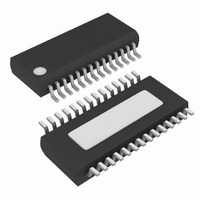
MAX3140EEI+T Maxim Integrated Products, MAX3140EEI+T Datasheet - Page 25

MAX3140EEI+T
Manufacturer Part Number
MAX3140EEI+T
Description
IC UART W/RS485 28-QSOP
Manufacturer
Maxim Integrated Products
Datasheet
1.MAX3140CEIT.pdf
(36 pages)
Specifications of MAX3140EEI+T
Features
Transceiver
Fifo's
8 Byte
Protocol
RS232, RS485
Voltage - Supply
4.75 V ~ 5.25 V
With Irda Encoder/decoder
Yes
With False Start Bit Detection
Yes
With Cmos
Yes
Mounting Type
Surface Mount
Package / Case
28-QSOP
Lead Free Status / RoHS Status
Lead free / RoHS Compliant
The receivers of the MAX3140, when operating in
115kbps or 500kbps mode, incorporate input filtering in
addition to input hysteresis. This filtering enhances
noise immunity with differential signals that have very
slow rise and fall times. Receiver propagation delay
increases by 20% due to this filtering.
Occasionally, twisted-pair lines are connected back-
ward from normal orientation. The MAX3140 has two
pins that invert the phase of the driver and the receiver
to correct for this problem. For normal operation, drive
TXP and RXP low, connect them to ground, or leave
them unconnected (internal pull-down). To invert the
driver phase, drive TXP high or connect it to V
invert the receiver phase, drive RXP high or connect it
to V
when RXP is high.
The MAX3140 includes an oscillator circuit derived
from an external crystal for baud-rate generation. For
standard baud rates, use a 1.8432MHz or 3.6864MHz
crystal. The 1.8432MHz crystal results in lower operat-
ing current; however, the 3.6864MHz crystal may be
more readily available in surface-mount packages.
Ceramic resonators are low-cost alternatives to crystals
and operate similarly, though the Q and accuracy are
lower. Some ceramic resonators are available with inte-
gral load capacitors, which can further reduce cost.
The trade-off between crystals and ceramic resonators
is in initial frequency accuracy and temperature drift.
Keep the total error in the baud-rate generator below
Table 8. Component and Supplier List
SPI/MICROWIRE-Compatible UART with Integrated
Through-Hole Crystal
(HC-49/U)
Through-Hole
Ceramic Resonator
Through-Hole Crystal
(HC-49/US)
SMT Crystal
SMT Ceramic
Resonator
CC
DESCRIPTION
. Note that the receiver threshold is positive
Applications Information
______________________________________________________________________________________
True Fail-Safe RS-485/RS-422 Transceivers
Crystals, Oscillators, and
FREQUENCY
1.8432
1.8432
3.6864
3.6864
3.6864
(MHz)
Ceramic Resonators
Phase Control Circuitry
Receiver Input Filtering
C1, C2 (pF)
TYPICAL
(integral)
None
25
47
33
39
CC
. To
ECS International, Inc.
Murata North America
ECS International, Inc.
ECS International, Inc.
AVX/Kyocera
1% for reliable operation with other systems. This is
accomplished easily with a crystal, and in most cases
is achieved with ceramic resonators. Table 8 lists differ-
ent types of crystals and resonators and their suppliers.
The MAX3140’s oscillator supports parallel-resonant
mode crystals and ceramic resonators, or can be driven
from an external clock source. Internally, the oscillator
consists of an inverting amplifier with its input (X1) tied
to its output (X2) by a bias network that self-biases the
inverter at approximately V
circuit, usually a crystal from X2 to X1, provides 180° of
phase shift, causing the circuit to oscillate. As shown in
the standard application circuit, the crystal or resonator
is connected between X1 and X2, with the load capaci-
tance for the crystal being the series combination of C1
and C2. For example, for a 1.8432MHz crystal with a
specified load capacitance of 11pF, use 22pF capaci-
tors on either side of the crystal to ground. Series-res-
onant mode crystals have a slight frequency error,
typically oscillating 0.03% higher than specified series-
resonant frequency when operated in parallel mode.
Note: It is very important to keep crystal, resonator,
and load-capacitor leads and traces as short and
direct as possible. Make the X1 and X2 trace lengths
and ground tracks short, with no intervening traces.
This helps minimize parasitic capacitance and noise
pickup in the oscillator, and reduces EMI. Minimize
capacitive loading on X2 to minimize supply current.
The MAX3140’s X1 input can be driven directly by an
external CMOS clock source. The trip level is approxi-
mately equal to V
mode. If a TTL or non-CMOS clock source is used, AC-
couple with a 10nF capacitor to X1. A 2V peak-to-peak
swing on the input is required for reliable operation.
SUPPLIER
CC
/2. Make no connection to X2 in this
ECS-18-13-1
CSA1.84MG
ECS-36-18-4
ECS-36-20-5P
PBRC-3.68B
NUMBER
CC
PART
/2. The external feedback
(913) 782-7787
(800) 831-9172
(913) 782-7787
(913) 782-7787
(803) 448-9411
NUMBER
PHONE
25


