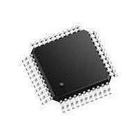
SC28L92A1B NXP Semiconductors, SC28L92A1B Datasheet - Page 33

SC28L92A1B
Manufacturer Part Number
SC28L92A1B
Description
UART Interface IC UART DUAL W/FIFO
Manufacturer
NXP Semiconductors
Type
Dual UARTr
Datasheet
1.SC28L92A1B557.pdf
(73 pages)
Specifications of SC28L92A1B
Number Of Channels
2
Data Rate
230.4 Kbps
Supply Voltage (max)
5 V
Supply Voltage (min)
3.3 V
Supply Current
25 mA
Maximum Operating Temperature
+ 85 C
Minimum Operating Temperature
- 40 C
Package / Case
PQFP-44
Description/function
Single-chip CMOS-LSI communications device
Mounting Style
SMD/SMT
Operating Supply Voltage
3.3 V, 5 V
Lead Free Status / Rohs Status
Details
Other names
SC28L92A1B,557
Available stocks
Company
Part Number
Manufacturer
Quantity
Price
Part Number:
SC28L92A1B
Manufacturer:
PHILIPS/飞利浦
Quantity:
20 000
Company:
Part Number:
SC28L92A1B,528
Manufacturer:
NXP Semiconductors
Quantity:
10 000
Company:
Part Number:
SC28L92A1B,551
Manufacturer:
NXP Semiconductors
Quantity:
10 000
Company:
Part Number:
SC28L92A1B,557
Manufacturer:
NXP Semiconductors
Quantity:
10 000
Company:
Part Number:
SC28L92A1BS,528
Manufacturer:
NXP Semiconductors
Quantity:
10 000
Company:
Part Number:
SC28L92A1BS,551
Manufacturer:
NXP Semiconductors
Quantity:
10 000
NXP Semiconductors
Table 35.
See
SC28L92_7
Product data sheet
CSR[7:4]
CSR[3:0]
0000
0001
0010
0011
0100
0101
0110
0111
1000
1001
1010
1011
1100
1101
Table 36
Baud rate (based on a 3.6864 MHz crystal clock)
for bit rate characteristics.
7.3.2.1 Clock Select Register channel A (CSRA)
7.3.2 Clock select registers
MR0[0] = 0 (Normal mode)
ACR[7] = 0
50
110
134.5
200
300
600
1,200
1,050
2,400
4,800
7,200
9,600
38,400
Timer
Table 33.
Table 34.
Bit
7 to 4
3 to 0
7
Symbol
-
-
ACR[7] = 1
75
110
134.5
150
300
600
1,200
2,000
2,400
4,800
1,800
9,600
19,200
Timer
receiver clock select code
CSRA - Clock select register channel A (address 0x1) and
CSRB - Clock select register channel B (address 0x9) bit allocation
CSRA - Clock select register channel A (address 0x1) bit description
6
Description
Receiver clock select. The baud rate clock for the channel A receiver is as
shown in
The receiver clock is always a 16 clock except for CSRA[7:4] = 1111
Transmitter clock select. The baud rate clock for the channel A transmitter is
as shown in
The transmitter clock is always a 16 clock except for CSRA[3:0] = 1111
Rev. 07 — 19 December 2007
1110 = IP4 - 16
1111 = IP4 - 1
1110 = IP3 - 16
1111 = IP3 - 1
3.3 V/5.0 V Dual Universal Asynchronous Receiver/Transmitter
MR0[0] = 1 (Extended mode I)
ACR[7] = 0
300
110
134.5
1200
1800
3600
7200
1,050
14,400
28,800
7,200
57,600
230,400
Timer
5
Table
Table
35, except as follows:
35, except as follows:
4
ACR[7] = 1
450
110
134.5
900
1800
3600
7,200
2,000
14,400
28,800
1,800
57,600
115,200
Timer
3
transmitter clock select code
MR0[2] = 1 (Extended mode II)
ACR[7] = 0
4,800
880
1,076
19.200
28.800
57.600
115,200
1,050
57,600
4,800
57,600
9,600
38,400
Timer
2
SC28L92
© NXP B.V. 2007. All rights reserved.
1
ACR[7] = 1
7,200
880
1,076
14.400
28.800
57.600
115,200
2,000
57,600
4,800
14,400
9,600
19,200
Timer
33 of 73
0


