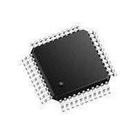
SC28L92A1B NXP Semiconductors, SC28L92A1B Datasheet - Page 15

SC28L92A1B
Manufacturer Part Number
SC28L92A1B
Description
UART Interface IC UART DUAL W/FIFO
Manufacturer
NXP Semiconductors
Type
Dual UARTr
Datasheet
1.SC28L92A1B557.pdf
(73 pages)
Specifications of SC28L92A1B
Number Of Channels
2
Data Rate
230.4 Kbps
Supply Voltage (max)
5 V
Supply Voltage (min)
3.3 V
Supply Current
25 mA
Maximum Operating Temperature
+ 85 C
Minimum Operating Temperature
- 40 C
Package / Case
PQFP-44
Description/function
Single-chip CMOS-LSI communications device
Mounting Style
SMD/SMT
Operating Supply Voltage
3.3 V, 5 V
Lead Free Status / Rohs Status
Details
Other names
SC28L92A1B,557
Available stocks
Company
Part Number
Manufacturer
Quantity
Price
Part Number:
SC28L92A1B
Manufacturer:
PHILIPS/飞利浦
Quantity:
20 000
Company:
Part Number:
SC28L92A1B,528
Manufacturer:
NXP Semiconductors
Quantity:
10 000
Company:
Part Number:
SC28L92A1B,551
Manufacturer:
NXP Semiconductors
Quantity:
10 000
Company:
Part Number:
SC28L92A1B,557
Manufacturer:
NXP Semiconductors
Quantity:
10 000
Company:
Part Number:
SC28L92A1BS,528
Manufacturer:
NXP Semiconductors
Quantity:
10 000
Company:
Part Number:
SC28L92A1BS,551
Manufacturer:
NXP Semiconductors
Quantity:
10 000
NXP Semiconductors
SC28L92_7
Product data sheet
6.2.2 Baud rate generator
6.2.3 Counter/timer
6.2.4 Timer mode
The baud rate generator operates from the oscillator or external clock input at the X1 input
and is capable of generating 28 commonly used data communications baud rates ranging
from 50 kBd to 38.4 kBd. Programming bit 0 of MR0 to a logic 1 gives additional baud
rates of 57.6 kBd, 115.2 kBd and 230.4 kBd (500 kHz with X1 at 8.0 MHz). Note that the
MR0A[2:0] control this change and that the change applies to both channels. MR0B[2:0]
are reserved.
The baud rates are based on an input frequency of 3.6864 MHz. Changing the X1
frequency will change all baud rates by ratio of 3.6864 MHz to the new frequency. All rates
generated by the BRG will be in the 16 mode. The clock outputs from the BRG are at 16
the actual baud rate.
The counter/timer can be used as a timer to produce a 16 clock for any other baud rate
by counting down the crystal clock or an external clock. The four clock selectors allow the
independent selection, for each receiver and transmitter, of any of these baud rates or
external timing signal. The use of the counter/timer also requires the generation of a
frequency 16 of the baud rate. See
The Counter/timer is a 16-bit programmable divider that operates in one of three modes:
counter, timer and time-out. In the timer mode it generates a square wave. In the counter
mode it generates a time delay. In the time-out mode it monitors the time between
received characters. The C/T uses the numbers loaded into the Counter/Timer Lower
Register (CTLR) and the Counter/Timer Upper Register (CTUR) as its divisor.
The counter/timer clock source and mode of operation (counter or timer) is selected by the
Auxiliary Control Register bits 6 to 4 (ACR[6:4]). The output of the counter/timer may be
used for a baud rate and/or may be output to the OP pins for some external function that
may be totally unrelated to data transmission. The counter/timer also sets the
counter/timer ready bit in the Interrupt Status Register (ISR) when its output transitions
from logic 1 to logic 0. A register read address (see
counter/timer command and a second register read address is reserved to issue a stop
command. The value of D[7:0] is ignored. The START command always loads the
contents of CTUR, CTLR to the counting registers. The STOP command always resets
the ISR[3] bit in the interrupt status register.
In the timer mode a symmetrical square wave is generated whose half period is equal in
time to division of the selected counter/timer clock frequency by the 16-bit number loaded
in the CTLR CTUR. Thus, the frequency of the counter/timer output will be equal to the
counter/timer clock frequency divided by twice the value of the CTUR CTLR. While in the
timer mode the ISR bit 3 (ISR[3]) will be set each time the counter/timer transitions from
logic 1 to logic 0 (HIGH-to-LOW). This continues regardless of issuance of the stop
counter command. ISR[3] is reset by the stop counter command.
Note: Reading of the CTU and CTL registers in the timer mode is not meaningful. When
the C/T is used to generate a baud rate and the C/T is selected through the CSR then the
receivers and/or transmitter will be operating in the 16 mode. Calculation for the
number n to program the counter/timer upper and lower registers is shown in
The value of the divisor n is
Rev. 07 — 19 December 2007
3.3 V/5.0 V Dual Universal Asynchronous Receiver/Transmitter
Section
6.2.3.
Table
4) is reserved to issue a start
SC28L92
© NXP B.V. 2007. All rights reserved.
Equation
15 of 73
1.


