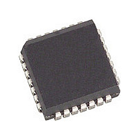
SL811HST Cypress Semiconductor Corp, SL811HST Datasheet - Page 10

SL811HST
Manufacturer Part Number
SL811HST
Description
Manufacturer
Cypress Semiconductor Corp
Datasheet
1.SL811HST.pdf
(32 pages)
Specifications of SL811HST
Operating Temperature (min)
0C
Operating Temperature Classification
Commercial
Package Type
PLCC
Rad Hardened
No
Lead Free Status / Rohs Status
Not Compliant
Available stocks
Company
Part Number
Manufacturer
Quantity
Price
Company:
Part Number:
SL811HST
Manufacturer:
CYP
Quantity:
3 000
Company:
Part Number:
SL811HST
Manufacturer:
CYPRESS
Quantity:
3 000
Company:
Part Number:
SL811HST
Manufacturer:
CYPRESS
Quantity:
5
Part Number:
SL811HST
Manufacturer:
CYPRESS/赛普拉斯
Quantity:
20 000
Company:
Part Number:
SL811HST-1.5
Manufacturer:
CYP
Quantity:
2 340
Part Number:
SL811HST-1.5
Manufacturer:
CYPRESS/赛普拉斯
Quantity:
20 000
Company:
Part Number:
SL811HST-AC
Manufacturer:
Cypress Semiconductor Corp
Quantity:
10 000
Company:
Part Number:
SL811HST-AXC
Manufacturer:
Cypress Semiconductor Corp
Quantity:
10 000
Part Number:
SL811HST-AXC
Manufacturer:
CYPRESS/赛普拉斯
Quantity:
20 000
3.1.3.6 Current Data Set Register/Hardware Revision/SOF Counter LOW [Address = 0Eh]
This register has two modes: a Read from this register indicates the current SL811HS silicon revision.
Table 3-15. Hardware Revision when READ [Address 0Eh]
Writing to this register will set up auto generation of SOF to all connected peripherals. This counter is based on the 12-MHz clock
and is not dependent on the crystal frequency. To set up a 1-ms timer interval, the software must set up both SOF counter registers
to the proper values.
Table 3-16. SOF Counter LOW Address when WRITTEN [Address 0Eh]
3.1.3.7 SOF Counter HIGH/Control Register 2 [Address = 0Fh]
When read, this register will return the value of the SOF counter divided by 64. The software should use this register to determine
the available bandwidth in the current frame before initiating any USB transfer. In this way, the user will be able to avoid babble
conditions on the USB. For example, to determine the available bandwidth left in a frame:
Maximum number of clock ticks in 1-ms time frame is 12000 (1 count per 12-MHz clock period, or approximately 84 ns.) The
value read back in Register 0FH is the (count × 64) × 84 ns = time remaining in current frame. USB bit time = one 12-MHz period.
Note: Any Write to the 0Fh register will clear the internal frame counter. Register 0Fh must be written at least once after power-
up. The internal frame counter is incremented after every SOF timer tick. The internal frame counter is an 11-bit counter, which
is used to track the frame number. The frame number is incremented after each timer tick. Its contents are transmitted to the slave
every millisecond in a SOF packet.
Document 38-08008 Rev. *B
Value of register 0FH
BBH
BAH
Bit Position
Example: To set up SOF for 1-ms interval, SOF counter register 0Eh should be set to E0h.
SOF7
Bit 7
Bit Position
Bit 7
6
5
4
3
2
1
0
7-4
3-2
1-0
Bit Name
Device Detect/Resume Device Detect/Resume Interrupt.
Insert/Remove
SOF timer
Reserved
Reserved
USB-B
USB-A
SOF6
Bit 6
Bit 6
Hardware Revision
Bit Name
Hardware Revision
Reserved
Reserved
Available bit times left are between
12000 bits to 11968 (187 × 64) bits
11968 bits to 11904 (186 × 64) bits
SOF5
Bit 5
Bit 5
Function
Bit 6 is shared between Device Detection status and Resume detection interrupt. When
bit-6 of register 05h is set to one, this bit will be the Resume detection Interrupt bit.
Otherwise, this bit is used to indicate the presence of a Device, “1” = device “Not
present” and “0” = device “Present.” In this mode this bit should be checked along with
bit 5 to determine whether a device has been inserted or removed.
Device Insert/Remove Detection.
Bit 5 is provided to support USB cable Insertion/Removal for the SL811HS in Host
Mode. This bit is set when a transition from SE0 to IDLE (device inserted) or from IDLE
to SE0 (device removed) occurs on the bus.
1 = Interrupt on SOF Timer.
0
0
USB-B Done Interrupt. (See description in Interrupt Enable Register [address 06h]).
USB-A Done Interrupt. (See description in Interrupt Enable Register [address 06h]).
Function
SL11H Read = 0H, SL811HS rev1.2 Read = 1H, SL811HS rev1.5 Read = 2.
Read will be zero.
Reserved for slave.
SOF4
Bit 4
Bit 4
SOF3
Bit 3
Bit 3
SOF2
Bit 2
Bit 2
Reserved
SOF1
Bit 1
Bit 1
SL811HS
Page 10 of 32
SOF0
Bit 0
Bit 0
[+] Feedback


