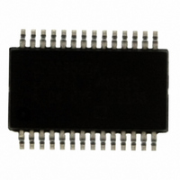
CY8C9520A-24PVXI Cypress Semiconductor Corp, CY8C9520A-24PVXI Datasheet - Page 20

CY8C9520A-24PVXI
Manufacturer Part Number
CY8C9520A-24PVXI
Description
IC I/O EXPANDER I2C 20B 28SSOP
Manufacturer
Cypress Semiconductor Corp
Datasheet
1.CY8C9520A-24PVXI.pdf
(32 pages)
Specifications of CY8C9520A-24PVXI
Package / Case
28-SSOP
Interface
I²C
Number Of I /o
20
Interrupt Output
Yes
Frequency - Clock
100KHz
Voltage - Supply
3 V ~ 5.25 V
Operating Temperature
-40°C ~ 85°C
Mounting Type
Surface Mount
Includes
EEPROM, POR, PWM, WDT
Processor Series
CY8C95x0A
Core
M8C
Data Bus Width
8 bit
Maximum Clock Frequency
24 MHz
Number Of Programmable I/os
20
Operating Supply Voltage
3 V to 5.25 V
Maximum Operating Temperature
+ 85 C
Mounting Style
SMD/SMT
Development Tools By Supplier
CY3242-IOX, CY3242-IOXLite
Minimum Operating Temperature
- 40 C
On-chip Adc
8 bit
Program Memory Type
EEPROM
Program Memory Size
32 KB
Lead Free Status / RoHS Status
Lead free / RoHS Compliant
For Use With
428-2023 - KIT EVAL PSOC I2C PORT EXP428-1911 - KIT EVAL PSOC I2C PORT EXP
Lead Free Status / Rohs Status
Lead free / RoHS Compliant
Other names
428-2015-5
Available stocks
Company
Part Number
Manufacturer
Quantity
Price
Company:
Part Number:
CY8C9520A-24PVXI
Manufacturer:
LT
Quantity:
1 378
Part Number:
CY8C9520A-24PVXI
Manufacturer:
CYPRESS/赛普拉斯
Quantity:
20 000
AC I
Table 28 lists guaranteed maximum and minimum specifications for the voltage and temperature ranges: 4.75V to 5.25V and -40°C
≤ T
guidance only or unless otherwise specified.
Table 28. AC Characteristics of the I
AC EEPROM Write Specifications
Table 29 lists guaranteed maximum and minimum specifications for the voltage and temperature ranges: 4.75V to 5.25V and -40°C
≤ T
guidance only or unless otherwise specified.
Table 29. AC EEPROM Write Specifications
Document Number: 38-12036 Rev. *E
T
T
F
T
T
T
T
T
T
T
T
T
I2C_SDA
I2C_SCL
Symbol
EEPROMWrite_Hot
EEPROMWrite_Cold
SCLI2C
HDSTAI2C
LOWI2C
HIGHI2C
SUSTAI2C
HDDATI2C
SUDATI2C
SUSTOI2C
BUFI2C
SPI2C
A
A
2
≤ 85°C, or 3.0V to 3.6V and -40°C ≤ T
≤ 85°C, or 3.0V to 3.6V and -40°C ≤ T
START Condition
C Specifications
Symbol
SCL clock frequency
Hold time (repeated) START condition. After
this period, the first clock pulse is generated.
LOW period of the SCL clock
HIGH period of the SCL clock
Setup time for a repeated START condition
Data hold time
Data setup time
Setup time for STOP condition
Bus free time between a STOP and START
Condition
Pulse width of spikes are suppressed by the
input filter.
S
T
HDSTAI2C
T
T
EEPROM Erase + Write time
EEPROM Erase + Write time
HIGHI2C
SUDATI2C
Figure 9. Definition for Timing for Fast/Standard Mode on the I
Description
Description
T
LOWI2C
2
C SDA and SCL Pins
A
A
≤ 85°C, respectively. Typical parameters apply to 5V and 3.3V at 25°C and are for design
≤ 85°C, respectively. Typical parameters apply to 5V and 3.3V at 25°C and are for design
T
HDDATI2C
T
Repeated START Condition
SUSTAI2C
Standard Mode
Min
Min
250
4.0
4.7
4.0
4.7
4.0
4.7
–
–
0
0
–
Sr
Max
100
–
–
–
–
–
–
–
–
–
Typ
–
–
100
Min
0.6
1.3
0.6
0.6
0.6
1.3
Fast Mode
0
0
0
Max
100
200
3
T
CY8C9540A, CY8C9560A
Max
SPI2C
–
–
–
–
–
–
–
–
–
–
T
Units
SUSTOI2C
ms
ms
2
C Bus
Units
STOP Condition
kHz
μs
μs
μs
μs
μs
ns
μs
μs
ns
0°C ≤ Tj ≤ 100°C
-40°C ≤ Tj ≤ 0°C
P
CY8C9520A
T
Notes
Page 20 of 32
BUFI2C
Notes
S
[+] Feedback


