20-101-1306 Rabbit Semiconductor, 20-101-1306 Datasheet - Page 62
20-101-1306
Manufacturer Part Number
20-101-1306
Description
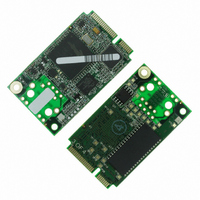
CORE MODULE RCM5750
Manufacturer
Rabbit Semiconductor
Type
Serial to Ethernetr
Datasheet
1.20-101-1306.pdf
(119 pages)
Specifications of 20-101-1306
Module/board Type
MPU Core Module
Number Of I/os
32
Ethernet Connection Type
10/100 Base-T
Memory Type
Flash
Operating Voltage
3.3 V
Operating Current
70 mA
Operating Temperature Range
- 40 C to + 85 C
Board Size
30 mm x 51 mm x 3 mm
Product
Modules
For Use With/related Products
RCM5750
Lead Free Status / RoHS Status
Lead free / RoHS Compliant
Other names
316-1183


B.3 Ethernet
B.3.1 RJ-45
The Ethernet filter circuit is different between the Rabbit 5000 and Rabbit 6000 Ethernet designs.
If an RJ-45 jack is present on the MiniCore, then the appropriate circuitry is on the MiniCore. If
the interface board Ethernet RJ-45 is to be used, then a given interface board will support Ethernet
only for either the RCM5700 or RCM6700 family, but not both. The interface board supplied in
the Development Kit is properly configured for the MiniCore in the kit.
B.3.2 RCM6700 LEDs
The RCM6700/RCM6750 only support a single off-board Ethernet status LED, unlike the
RCM5700/RCM5750 which support two (LINK and ACT). The signal used as ACT on the
RCM5700 is replaced with +2.5 V for the Ethernet circuitry on the RCM6700. To provide the
same information, a combined LINK+ACT signal is used: off means no link, on means link, and
blink means activity. The on-board Ethernet LEDs on the RJ-45 jack behave identically in both
the RCM5700 and RCM6700.
If the RCM5700’s two-LED configuration is desired for a RCM6700-based design, the behavior
of the LINK+ACT signal must be changed to just LINK, and a GPIO pin must be assigned as the
ACT signal. The Interface Board is designed to support either PE3 or PE5 as the ACT signal, and
can be configured by defining macros and placing jumpers as shown in Table B-2.
The Ethernet LEDs are under software control on the RCM6700, so other configurations are pos-
sible as well. See the RCM6700-specific section of
details.
MiniCore RCM5700/RCM6700 User’s Manual
Single LED
Dual LEDs,
ACT is PE3
Dual LEDs,
ACT is PE5
Mode
Table B-2. Interface Board Ethernet LED Configuration for RCM6700
LINK off is no link
LINK on is link, blink
off for activity
LINK off is no link
LINK on is link
ACT off is no activity
ACT on is activity
(matches RCM5700)
Behavior
rabbit.com
Setting
JP80
4–6
1–3
4–6
1–2
4–6
LIB\Rabbit4000\TCPIP
None (default behavior)
ENET_ACTIVITY_ON_PE3
ENET_ACTIVITY_ON_PE5
Macros to define
folder for more
62
Related parts for 20-101-1306
Image
Part Number
Description
Manufacturer
Datasheet
Request
R

Part Number:
Description:
COMPUTER SGL-BRD BL2500 29.4MHZ
Manufacturer:
Rabbit Semiconductor
Datasheet:

Part Number:
Description:
COMPUTER SGL-BRD BL2500 29.4MHZ
Manufacturer:
Rabbit Semiconductor
Datasheet:

Part Number:
Description:
DISPLAY GRAPHIC 12KEY PROG OP670
Manufacturer:
Rabbit Semiconductor
Datasheet:
Part Number:
Description:
DISPLAY GRAPHIC 12KEY ETH OP6700
Manufacturer:
Rabbit Semiconductor
Datasheet:

Part Number:
Description:
COMPUTER SINGLE-BOARD BL2030
Manufacturer:
Rabbit Semiconductor
Part Number:
Description:
COMPUTER SGL-BOARD ETH BL2010
Manufacturer:
Rabbit Semiconductor

Part Number:
Description:
MODULE OP6810 W/O ETH/MEM EXPANS
Manufacturer:
Rabbit Semiconductor
Datasheet:
Part Number:
Description:
COMPUTER SINGLE-BOARD BL2020
Manufacturer:
Rabbit Semiconductor
Part Number:
Description:
COMPUTER BL2010 W/FRICTION LOCK
Manufacturer:
Rabbit Semiconductor
Part Number:
Description:
COMPUTER BL2020 W/FRICTION LOCK
Manufacturer:
Rabbit Semiconductor
Part Number:
Description:
COMPUTER SGL-BRD BL2500 44.2MHZ
Manufacturer:
Rabbit Semiconductor
Datasheet:
Part Number:
Description:
COMPUTER SGL-BOARD FULL BL2000
Manufacturer:
Rabbit Semiconductor

Part Number:
Description:
COMPUTER SINGLE-BOARD BL2110
Manufacturer:
Rabbit Semiconductor

Part Number:
Description:
COMPUTER SGL-BRD 29.4MHZ BL2610
Manufacturer:
Rabbit Semiconductor
Datasheet:
Part Number:
Description:
INTERFACE OP6800 512K FLASH&SRAM
Manufacturer:
Rabbit Semiconductor
Datasheet: