20-101-1306 Rabbit Semiconductor, 20-101-1306 Datasheet - Page 21
20-101-1306
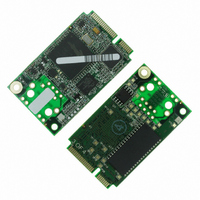
Manufacturer Part Number
20-101-1306
Description
CORE MODULE RCM5750
Manufacturer
Rabbit Semiconductor
Type
Serial to Ethernetr
Datasheet
1.20-101-1306.pdf
(119 pages)
Specifications of 20-101-1306
Module/board Type
MPU Core Module
Number Of I/os
32
Ethernet Connection Type
10/100 Base-T
Memory Type
Flash
Operating Voltage
3.3 V
Operating Current
70 mA
Operating Temperature Range
- 40 C to + 85 C
Board Size
30 mm x 51 mm x 3 mm
Product
Modules
For Use With/related Products
RCM5750
Lead Free Status / RoHS Status
Lead free / RoHS Compliant
Other names
316-1183


The Digital I/O accessory board needs to be installed to run the
TOSERIAL.C
ment Kit.
To install the Digital I/O accessory board, insert the strip of header pins included with the acces-
sory board into the socket at J12 on the bottom side of the Digital I/O accessory board. Then line
up the Digital I/O accessory board with the Interface Board standoffs/connectors and install the
Digital I/O accessory board pins into socket J2 on the Interface Board. Secure the Digital I/O
accessory board with the long plastic standoffs/connectors from above as shown in Figure 3-6.
Pins 1–2, 3–4, 5–6, and 7–8 on headers JP5 and JP8 on the Digital I/O accessory board must be
jumpered. Pins 2–4 and 3–5 on header JP7 on the Digital I/O accessory board must also be jump-
ered.
•
MiniCore RCM5700/RCM6700 User’s Manual
SWITCHLEDS.C
lights LEDs DS1–DS4 when the corresponding pushbutton switch is pressed. LEDs DS1–DS2
on the Digital I/O accessory board are controlled by PA4–PA7, and switches S1–S4 are con-
trolled by PB4–PB7 respectively.
sample programs. This accessory board is included only with the Deluxe Develop-
—monitors switches S1, S2, S3, and S4 on the Digital I/O accessory board and
Figure 3-6. Install Digital I/O Accessory Board
rabbit.com
SWITCHLEDS.C
and the
SERIAL-
21
Related parts for 20-101-1306
Image
Part Number
Description
Manufacturer
Datasheet
Request
R

Part Number:
Description:
COMPUTER SGL-BRD BL2500 29.4MHZ
Manufacturer:
Rabbit Semiconductor
Datasheet:

Part Number:
Description:
COMPUTER SGL-BRD BL2500 29.4MHZ
Manufacturer:
Rabbit Semiconductor
Datasheet:

Part Number:
Description:
DISPLAY GRAPHIC 12KEY PROG OP670
Manufacturer:
Rabbit Semiconductor
Datasheet:
Part Number:
Description:
DISPLAY GRAPHIC 12KEY ETH OP6700
Manufacturer:
Rabbit Semiconductor
Datasheet:

Part Number:
Description:
COMPUTER SINGLE-BOARD BL2030
Manufacturer:
Rabbit Semiconductor
Part Number:
Description:
COMPUTER SGL-BOARD ETH BL2010
Manufacturer:
Rabbit Semiconductor

Part Number:
Description:
MODULE OP6810 W/O ETH/MEM EXPANS
Manufacturer:
Rabbit Semiconductor
Datasheet:
Part Number:
Description:
COMPUTER SINGLE-BOARD BL2020
Manufacturer:
Rabbit Semiconductor
Part Number:
Description:
COMPUTER BL2010 W/FRICTION LOCK
Manufacturer:
Rabbit Semiconductor
Part Number:
Description:
COMPUTER BL2020 W/FRICTION LOCK
Manufacturer:
Rabbit Semiconductor
Part Number:
Description:
COMPUTER SGL-BRD BL2500 44.2MHZ
Manufacturer:
Rabbit Semiconductor
Datasheet:
Part Number:
Description:
COMPUTER SGL-BOARD FULL BL2000
Manufacturer:
Rabbit Semiconductor

Part Number:
Description:
COMPUTER SINGLE-BOARD BL2110
Manufacturer:
Rabbit Semiconductor

Part Number:
Description:
COMPUTER SGL-BRD 29.4MHZ BL2610
Manufacturer:
Rabbit Semiconductor
Datasheet:
Part Number:
Description:
INTERFACE OP6800 512K FLASH&SRAM
Manufacturer:
Rabbit Semiconductor
Datasheet: