MSC8122TVT6400V Freescale Semiconductor, MSC8122TVT6400V Datasheet - Page 42
MSC8122TVT6400V
Manufacturer Part Number
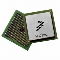
MSC8122TVT6400V
Description
IC DSP QUAD 16B 400MHZ 431FCPBGA
Manufacturer
Freescale Semiconductor
Series
MSC81xx StarCorer
Type
SC140 Corer
Datasheets
1.MSC8122TVT6400V.pdf
(48 pages)
2.MSC8122TVT6400V.pdf
(2 pages)
3.MSC8122TVT6400V.pdf
(8 pages)
Specifications of MSC8122TVT6400V
Interface
DSI, Ethernet, RS-232
Clock Rate
400MHz
Non-volatile Memory
External
On-chip Ram
1.436MB
Voltage - I/o
3.30V
Voltage - Core
1.10V
Operating Temperature
0°C ~ 90°C
Mounting Type
Surface Mount
Package / Case
431-FCPBGA
For Use With
MSC8122ADSE - KIT ADVANCED DEV SYSTEM 8122
Lead Free Status / RoHS Status
Lead free / RoHS Compliant
Available stocks
Company
Part Number
Manufacturer
Quantity
Price
Company:

Part Number:
MSC8122TVT6400V
Manufacturer:
Freescale
Quantity:
1 400
Company:
Part Number:
MSC8122TVT6400V
Manufacturer:
Freescale Semiconductor
Quantity:
10 000


Hardware Design Considerations
Note:
Note:
Note:
3.4
The external bus speed implemented in a system determines the speed of the SDRAM used on that bus. However, because of
differences in timing characteristics among various SDRAM manufacturers, you may have use a faster speed rated SDRAM to
assure efficient data transfer across the bus. For example, for 166 MHz operation, you may have to use 183 or 200 MHz
SDRAM. Always perform a detailed timing analysis using the MSC8122 bus timing values and the manufacturer specifications
for the SDRAM to ensure correct operation within your system design. The output delay listed in SDRAM specifications is
usually given for a load of 30 pF. Scale the number to your specific board load using the typical scaling number provided by
the SDRAM manufacturer.
42
•
•
•
•
•
•
•
The MSC8122 does not support DLL-enabled mode. For the following two clock schemes, ensure that the DLL is
disabled (that is, the DLLDIS bit in the Hard Reset Configuration Word is set).
If no system synchronization is required (for example, the design does not use SDRAM), you can use any of the
available clock modes.
In the
— Connect the oscillator output through a buffer to
— Connect
— Valid clock modes in this scheme are: 0, 7, 15, 19, 21, 23, 28, 29, 30, and 31.
In
connections:
— Connect the oscillator output through a buffer to
— Connect
— All clock modes are valid in this clock scheme.
See the Clock chapter in the MSC8122 Reference Manual for details.
If the 60x-compatible system bus is not used and SIUMCR[PBSE] is set,
should be pulled up.
The following signals:
used to configure the MSC8122 and are sampled on the deassertion of the
be tied to
When they are used,
be pulled up.
When the Ethernet controller is enabled and the SMII mode is selected,
externally to any signal line.
For details on configuration, see the MSC8122 User’s Guide and MSC8122 Reference Manual. For additional
information, refer to the MSC8122 Design Checklist (AN2787).
CLKOUT
between the clock buffer to the MSC8122 and the SDRAM is equal (that is, has a skew less than 100 ps).
guidelines:
– The maximum delay between the slave and
– The maximum load on
– Use a zero-delay buffer with a jitter less than 0.3 ns.
External SDRAM Selection
CLKIN
GND
synchronization mode (for 1.2 V devices),
the CLKIN
CLKOUT
synchronization mode, use the following connections:
or
V
DDH
INT_OUT
MSC8122 Quad Digital Signal Processor Data Sheet, Rev. 16
through a zero-delay buffer to the slave device (for example, SDRAM) using the following
SWTE, DSISYNC, DSI64, MODCK[1–2], CNFGS, CHIPID[0–3]
or through a pull-down or a pull-up resistor until the deassertion of the
buffer output to the slave device (for example, SDRAM) making sure that the delay path
(if SIUMCR[INTODC] is cleared),
CLKOUT
must not exceed 10 pF.
CLKOUT
CLKIN
CLKIN
CLKOUT
.
.
must not exceed 0.7 ns.
is the main clock to SDRAM. Use the following
NMI_OUT
GPIO10
PPBS
PORESET
, and
can be disconnected. Otherwise, it
IRQxx
and
GPIO14
signal. Therefore, they should
,
RSTCONF
(if not full drive) signals must
Freescale Semiconductor
must not be connected
PORESET
and
BM[0–2]
signal.
are
Related parts for MSC8122TVT6400V
Image
Part Number
Description
Manufacturer
Datasheet
Request
R

Part Number:
Description:
Manufacturer:
Freescale Semiconductor, Inc
Datasheet:
Part Number:
Description:
Manufacturer:
Freescale Semiconductor, Inc
Datasheet:
Part Number:
Description:
Manufacturer:
Freescale Semiconductor, Inc
Datasheet:
Part Number:
Description:
Manufacturer:
Freescale Semiconductor, Inc
Datasheet:
Part Number:
Description:
Manufacturer:
Freescale Semiconductor, Inc
Datasheet:
Part Number:
Description:
Manufacturer:
Freescale Semiconductor, Inc
Datasheet:
Part Number:
Description:
Manufacturer:
Freescale Semiconductor, Inc
Datasheet:
Part Number:
Description:
Manufacturer:
Freescale Semiconductor, Inc
Datasheet:
Part Number:
Description:
Manufacturer:
Freescale Semiconductor, Inc
Datasheet:
Part Number:
Description:
Manufacturer:
Freescale Semiconductor, Inc
Datasheet:
Part Number:
Description:
Manufacturer:
Freescale Semiconductor, Inc
Datasheet:
Part Number:
Description:
Manufacturer:
Freescale Semiconductor, Inc
Datasheet:
Part Number:
Description:
Manufacturer:
Freescale Semiconductor, Inc
Datasheet:
Part Number:
Description:
Manufacturer:
Freescale Semiconductor, Inc
Datasheet:
Part Number:
Description:
Manufacturer:
Freescale Semiconductor, Inc
Datasheet: