MSC8122TVT6400V Freescale Semiconductor, MSC8122TVT6400V Datasheet - Page 2
MSC8122TVT6400V
Manufacturer Part Number
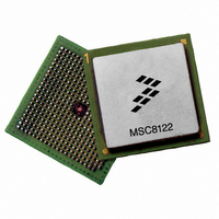
MSC8122TVT6400V
Description
IC DSP QUAD 16B 400MHZ 431FCPBGA
Manufacturer
Freescale Semiconductor
Series
MSC81xx StarCorer
Type
SC140 Corer
Datasheets
1.MSC8122TVT6400V.pdf
(48 pages)
2.MSC8122TVT6400V.pdf
(2 pages)
3.MSC8122TVT6400V.pdf
(8 pages)
Specifications of MSC8122TVT6400V
Interface
DSI, Ethernet, RS-232
Clock Rate
400MHz
Non-volatile Memory
External
On-chip Ram
1.436MB
Voltage - I/o
3.30V
Voltage - Core
1.10V
Operating Temperature
0°C ~ 90°C
Mounting Type
Surface Mount
Package / Case
431-FCPBGA
For Use With
MSC8122ADSE - KIT ADVANCED DEV SYSTEM 8122
Lead Free Status / RoHS Status
Lead free / RoHS Compliant
Available stocks
Company
Part Number
Manufacturer
Quantity
Price
Company:

Part Number:
MSC8122TVT6400V
Manufacturer:
Freescale
Quantity:
1 400
Company:
Part Number:
MSC8122TVT6400V
Manufacturer:
Freescale Semiconductor
Quantity:
10 000


1
2
3
4
5
6
7
List of Figures
Figure 1. MSC8122 Block Diagram . . . . . . . . . . . . . . . . . . . . . . . . 3
Figure 2. StarCore SC140 DSP Extended Core Block Diagram . . 3
Figure 3. MSC8122 Package, Top View . . . . . . . . . . . . . . . . . . . . 5
Figure 4. MSC8122 Package, Bottom View . . . . . . . . . . . . . . . . . . 6
Figure 5. Overshoot/Undershoot Voltage for V
Figure 6. Start-Up Sequence: V
Figure 7. Start-Up Sequence: V
Figure 8. Power-Up Sequence for V
Figure 9. Timing Diagram for a Reset Configuration Write . . . . . 21
2
Pin Assignments . . . . . . . . . . . . . . . . . . . . . . . . . . . . . . . . . . . .4
1.1
1.2
Electrical Characteristics . . . . . . . . . . . . . . . . . . . . . . . . . . . .13
2.1
2.2
2.3
2.4
2.5
Hardware Design Considerations . . . . . . . . . . . . . . . . . . . . . .39
3.1
3.2
3.3
3.4
3.5
Ordering Information. . . . . . . . . . . . . . . . . . . . . . . . . . . . . . . .43
Package Information. . . . . . . . . . . . . . . . . . . . . . . . . . . . . . . .44
Product Documentation . . . . . . . . . . . . . . . . . . . . . . . . . . . . .44
Revision History . . . . . . . . . . . . . . . . . . . . . . . . . . . . . . . . . . .45
FC-PBGA Ball Layout Diagrams . . . . . . . . . . . . . . . . . . .4
Signal List By Ball Location. . . . . . . . . . . . . . . . . . . . . . .7
Maximum Ratings . . . . . . . . . . . . . . . . . . . . . . . . . . . . .13
Recommended Operating Conditions. . . . . . . . . . . . . .14
Thermal Characteristics . . . . . . . . . . . . . . . . . . . . . . . .14
DC Electrical Characteristics . . . . . . . . . . . . . . . . . . . .15
AC Timings . . . . . . . . . . . . . . . . . . . . . . . . . . . . . . . . . .16
Start-up Sequencing Recommendations . . . . . . . . . . .39
Power Supply Design Considerations. . . . . . . . . . . . . .40
Connectivity Guidelines . . . . . . . . . . . . . . . . . . . . . . . .41
External SDRAM Selection . . . . . . . . . . . . . . . . . . . . . .42
Thermal Considerations . . . . . . . . . . . . . . . . . . . . . . . .43
Started with V
DDH
. . . . . . . . . . . . . . . . . . . . . . . . . . . . . 17
DD
DD
MSC8122 Quad Digital Signal Processor Data Sheet, Rev. 16
and V
Raised Before V
DDH
and V
DDH
Raised Together . . 17
IH
DD
and V
/V
Table of Contents
CCSYN
DDH
IL
with CLKIN
. . . . . . . 16
. . . . . 18
Figure 10.Internal Tick Spacing for Memory Controller Signals. . . 22
Figure 11.SIU Timing Diagram . . . . . . . . . . . . . . . . . . . . . . . . . . . 25
Figure 12.CLKOUT and CLKIN Signals. . . . . . . . . . . . . . . . . . . . . 26
Figure 13.DMA Signals . . . . . . . . . . . . . . . . . . . . . . . . . . . . . . . . . 27
Figure 14.Asynchronous Single- and Dual-Strobe Modes Read
Figure 15.Asynchronous Single- and Dual-Strobe Modes Write
Figure 16.Asynchronous Broadcast Write Timing Diagram . . . . . . 30
Figure 17.DSI Synchronous Mode Signals Timing Diagram . . . . . 31
Figure 18.TDM Inputs Signals . . . . . . . . . . . . . . . . . . . . . . . . . . . . 32
Figure 19.TDM Output Signals . . . . . . . . . . . . . . . . . . . . . . . . . . . 32
Figure 20.UART Input Timing . . . . . . . . . . . . . . . . . . . . . . . . . . . . 33
Figure 21.UART Output Timing . . . . . . . . . . . . . . . . . . . . . . . . . . . 33
Figure 22.Timer Timing . . . . . . . . . . . . . . . . . . . . . . . . . . . . . . . . . 34
Figure 23.MDIO Timing Relationship to MDC . . . . . . . . . . . . . . . . 34
Figure 24.MII Mode Signal Timing . . . . . . . . . . . . . . . . . . . . . . . . . 35
Figure 25.RMII Mode Signal Timing . . . . . . . . . . . . . . . . . . . . . . . 35
Figure 26.SMII Mode Signal Timing. . . . . . . . . . . . . . . . . . . . . . . . 36
Figure 27.GPIO Timing . . . . . . . . . . . . . . . . . . . . . . . . . . . . . . . . . 37
Figure 28.EE Pin Timing . . . . . . . . . . . . . . . . . . . . . . . . . . . . . . . . 37
Figure 29.Test Clock Input Timing Diagram. . . . . . . . . . . . . . . . . . 38
Figure 30.Boundary Scan (JTAG) Timing Diagram . . . . . . . . . . . . 38
Figure 31.Test Access Port Timing Diagram . . . . . . . . . . . . . . . . . 39
Figure 32.TRST Timing Diagram . . . . . . . . . . . . . . . . . . . . . . . . . . 39
Figure 33.Core Power Supply Decoupling. . . . . . . . . . . . . . . . . . . 40
Figure 34.V
Figure 35.MSC8122 Mechanical Information, 431-pin FC-PBGA
Timing Diagram . . . . . . . . . . . . . . . . . . . . . . . . . . . . . . . 29
Timing Diagram . . . . . . . . . . . . . . . . . . . . . . . . . . . . . . . 30
Package. . . . . . . . . . . . . . . . . . . . . . . . . . . . . . . . . . . . . 44
CCSYN
Bypass . . . . . . . . . . . . . . . . . . . . . . . . . . . . . . . 41
Freescale Semiconductor
Related parts for MSC8122TVT6400V
Image
Part Number
Description
Manufacturer
Datasheet
Request
R

Part Number:
Description:
Manufacturer:
Freescale Semiconductor, Inc
Datasheet:
Part Number:
Description:
Manufacturer:
Freescale Semiconductor, Inc
Datasheet:
Part Number:
Description:
Manufacturer:
Freescale Semiconductor, Inc
Datasheet:
Part Number:
Description:
Manufacturer:
Freescale Semiconductor, Inc
Datasheet:
Part Number:
Description:
Manufacturer:
Freescale Semiconductor, Inc
Datasheet:
Part Number:
Description:
Manufacturer:
Freescale Semiconductor, Inc
Datasheet:
Part Number:
Description:
Manufacturer:
Freescale Semiconductor, Inc
Datasheet:
Part Number:
Description:
Manufacturer:
Freescale Semiconductor, Inc
Datasheet:
Part Number:
Description:
Manufacturer:
Freescale Semiconductor, Inc
Datasheet:
Part Number:
Description:
Manufacturer:
Freescale Semiconductor, Inc
Datasheet:
Part Number:
Description:
Manufacturer:
Freescale Semiconductor, Inc
Datasheet:
Part Number:
Description:
Manufacturer:
Freescale Semiconductor, Inc
Datasheet:
Part Number:
Description:
Manufacturer:
Freescale Semiconductor, Inc
Datasheet:
Part Number:
Description:
Manufacturer:
Freescale Semiconductor, Inc
Datasheet:
Part Number:
Description:
Manufacturer:
Freescale Semiconductor, Inc
Datasheet: