MSC8122TVT6400V Freescale Semiconductor, MSC8122TVT6400V Datasheet - Page 39
MSC8122TVT6400V
Manufacturer Part Number
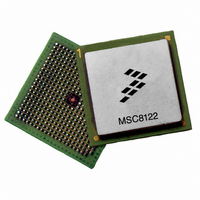
MSC8122TVT6400V
Description
IC DSP QUAD 16B 400MHZ 431FCPBGA
Manufacturer
Freescale Semiconductor
Series
MSC81xx StarCorer
Type
SC140 Corer
Datasheets
1.MSC8122TVT6400V.pdf
(48 pages)
2.MSC8122TVT6400V.pdf
(2 pages)
3.MSC8122TVT6400V.pdf
(8 pages)
Specifications of MSC8122TVT6400V
Interface
DSI, Ethernet, RS-232
Clock Rate
400MHz
Non-volatile Memory
External
On-chip Ram
1.436MB
Voltage - I/o
3.30V
Voltage - Core
1.10V
Operating Temperature
0°C ~ 90°C
Mounting Type
Surface Mount
Package / Case
431-FCPBGA
For Use With
MSC8122ADSE - KIT ADVANCED DEV SYSTEM 8122
Lead Free Status / RoHS Status
Lead free / RoHS Compliant
Available stocks
Company
Part Number
Manufacturer
Quantity
Price
Company:

Part Number:
MSC8122TVT6400V
Manufacturer:
Freescale
Quantity:
1 400
Company:
Part Number:
MSC8122TVT6400V
Manufacturer:
Freescale Semiconductor
Quantity:
10 000


3
The following sections discuss areas to consider when the MSC8122 device is designed into a system.
3.1
Use the following guidelines for start-up and power-down sequences:
Note:
External voltage applied to any input line must not exceed the I/O supply
power-up. Some designs require pull-up voltages applied to selected input lines during power-up for configuration purposes.
This is an acceptable exception to the rule. However, each such input can draw up to 80 mA per input pin per device in the
system during start-up.
During the power-up sequence, if V
device ESD protection circuits to the V
by more than 0.8 V. Design the power supply to prevent or minimize this effect using one of the following optional methods:
Freescale Semiconductor
•
•
•
Assert
required minimum power levels. This can be implemented via weak pull-down resistors.
CLKIN
start toggling before the deassertion of
If possible, bring up
V
voltage levels down together. If that is not possible reverse the power-up sequence, with
then
This recommended power sequencing for the MSC8122 is different from the MSC8102. See Section 2.5.2 for
start-up timing specifications.
DDH
(Input)
(Input)
Hardware Design Considerations
TRST
TCK
Start-up Sequencing Recommendations
V
.
(Output)
(Output)
DD
V
PORESET
can be held low or allowed to toggle during the beginning of the power-up sequence. However,
(Input)
(Input)
DDH
TMS
TDO
TDO
/
TCK
V
TDI
CCSYN
should not exceed
.
and
V
MSC8122 Quad Digital Signal Processor Data Sheet, Rev. 16
V
DD
TRST
IL
/
V
DD
CCSYN
712
Figure 31. Test Access Port Timing Diagram
before applying power and keep the signals driven low until the power reaches the
DDH
rises before V
V
DD
713
and
supply. The ESD protection diode can allow this to occur when V
Figure 32. TRST Timing Diagram
/
V
711
CCSYN
710
V
PORESET
DDH
together. If it is not possible, raise
until
DDH
V
(see Figure 6), current can pass from the V
and after both power supplies have reached nominal voltage levels.
DD
/
V
CCSYN
Output Data Valid
reaches its nominal voltage level. Similarly, bring both
V
708
Input Data Valid
DDH
by more than 0.8 V at any time, including during
V
V
IH
DD
709
/
V
CCSYN
V
DDH
first and then bring up
DD
going down first and
supply through the
DD
exceeds V
CLKIN
must
DDH
39
Related parts for MSC8122TVT6400V
Image
Part Number
Description
Manufacturer
Datasheet
Request
R

Part Number:
Description:
Manufacturer:
Freescale Semiconductor, Inc
Datasheet:
Part Number:
Description:
Manufacturer:
Freescale Semiconductor, Inc
Datasheet:
Part Number:
Description:
Manufacturer:
Freescale Semiconductor, Inc
Datasheet:
Part Number:
Description:
Manufacturer:
Freescale Semiconductor, Inc
Datasheet:
Part Number:
Description:
Manufacturer:
Freescale Semiconductor, Inc
Datasheet:
Part Number:
Description:
Manufacturer:
Freescale Semiconductor, Inc
Datasheet:
Part Number:
Description:
Manufacturer:
Freescale Semiconductor, Inc
Datasheet:
Part Number:
Description:
Manufacturer:
Freescale Semiconductor, Inc
Datasheet:
Part Number:
Description:
Manufacturer:
Freescale Semiconductor, Inc
Datasheet:
Part Number:
Description:
Manufacturer:
Freescale Semiconductor, Inc
Datasheet:
Part Number:
Description:
Manufacturer:
Freescale Semiconductor, Inc
Datasheet:
Part Number:
Description:
Manufacturer:
Freescale Semiconductor, Inc
Datasheet:
Part Number:
Description:
Manufacturer:
Freescale Semiconductor, Inc
Datasheet:
Part Number:
Description:
Manufacturer:
Freescale Semiconductor, Inc
Datasheet:
Part Number:
Description:
Manufacturer:
Freescale Semiconductor, Inc
Datasheet: