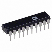
AD670JN Analog Devices Inc, AD670JN Datasheet - Page 8

AD670JN
Manufacturer Part Number
AD670JN
Description
IC ADC 8BIT SGNL COND 20-DIP
Manufacturer
Analog Devices Inc
Datasheet
1.AD670JNZ.pdf
(12 pages)
Specifications of AD670JN
Rohs Status
RoHS non-compliant
Number Of Bits
8
Sampling Rate (per Second)
10k
Data Interface
Parallel
Number Of Converters
1
Power Dissipation (max)
450mW
Voltage Supply Source
Single Supply
Operating Temperature
0°C ~ 70°C
Mounting Type
Through Hole
Package / Case
20-DIP (0.300", 7.62mm)
Available stocks
Company
Part Number
Manufacturer
Quantity
Price
Part Number:
AD670JN
Manufacturer:
ADI/亚德诺
Quantity:
20 000
Company:
Part Number:
AD670JNZ
Manufacturer:
DIODES
Quantity:
12 000
AD670
The R/W line is used to direct the converter to start a conver-
sion (R/W low) or read data (R/W high). The relative sequenc-
ing of the three control signals (R/W, CE, CS) is unimportant.
However, when all three signals remain low for at least 300 ns
(t
place.
Once a conversion is started and the STATUS line goes high,
convert start commands will be ignored until the conversion
cycle is complete. The output data buffer cannot be enabled
during a conversion.
Read Cycle
Figure 9 shows the timing for the data read operation. The data
outputs are in a high impedance state until a read cycle is initi-
ated. To begin the read cycle, R/W is brought high. During a
read cycle, the minimum pulse length for CE and CS is a func-
tion of the length of time required for the output data to be
valid. The data becomes valid and is available to the data bus in
a maximum of 250 ns. This delay between the high impedance
state and valid data is the maximum bus access time or t
Bringing CE or CS high during valid data ends the read cycle.
The outputs remain valid for a minimum of 25 ns (t
turn to the high impedance state after a delay, t
maximum.
W
), STATUS will go high to signal that a conversion is taking
Figure 8. Write/Convert Start Timing
Figure 9. Read Cycle Timing
DT
, of 150 ns
DH
) and re-
TD
.
–8–
STAND-ALONE OPERATION
The AD670 can be used in a “stand-alone” mode, which is use-
ful in systems with dedicated input ports available. Two typical
conditions are described and illustrated by the timing diagrams
which follow.
Single Conversion, Single Read
When the AD670 is used in a stand-alone mode, CS and CE
should be tied together. Conversion will be initiated by bringing
R/W low. Within 700 ns, a conversion will begin. The R/W
pulse should be brought high again once the conversion has
started so that the data will be valid upon completion of the
conversion. Data will remain valid until CE and CS are brought
high to indicate the end of the read cycle or R/W goes low. The
timing diagram is shown in Figure 10.
Continuous Conversion, Single Read
A variety of applications may call for the A/D to be read after
several conversions. In process control systems, this is often the
case since a reading from a sensor may only need to be updated
every few conversions. Figure 11 shows the timing relationships.
Once again, CE and CS should be tied together. Conversion
will begin when the R/W signal is brought low. The device will
convert repeatedly as indicated by the status line. A final con-
version will take place once the R/W line has been brought high.
The rising edge of R/W must occur while STATUS is high. R/W
should not return high while STATUS is low since the circuit is
in a reset state prior to the next conversion. Since the rising
edge of R/W must occur while STATUS is high, R/W’s length
must be a minimum of 10.25 s (t
upon completion of the conversion and will remain so until the
CE and CS lines are brought high indicating the end of the read
cycle or R/W goes low initiating a new series of conversions.
Figure 11. Stand-Alone Mode Continuous Conversion/
Single Read
Figure 10. Stand-Alone Mode Single Conversion/
Single Read
C
+ t
TD
). Data becomes valid
REV. A


