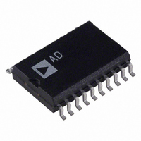
AD73311LAR Analog Devices Inc, AD73311LAR Datasheet - Page 24

AD73311LAR
Manufacturer Part Number
AD73311LAR
Description
IC ANALOG FRONT END 20-SOIC
Manufacturer
Analog Devices Inc
Datasheet
1.AD73311LAR.pdf
(36 pages)
Specifications of AD73311LAR
Rohs Status
RoHS non-compliant
Number Of Bits
16
Number Of Channels
2
Power (watts)
50mW
Voltage - Supply, Analog
3V
Voltage - Supply, Digital
3V
Package / Case
20-SOIC (7.5mm Width)
Single Supply Voltage (min)
2.7V
Single Supply Voltage (max)
3.3V
Package Type
SOIC W
Lead Free Status / RoHS Status
Not Compliant
Available stocks
Company
Part Number
Manufacturer
Quantity
Price
Part Number:
AD73311LAR
Manufacturer:
ADI/亚德诺
Quantity:
20 000
Company:
Part Number:
AD73311LARS
Manufacturer:
AD
Quantity:
12
Part Number:
AD73311LARS
Manufacturer:
ADI/亚德诺
Quantity:
20 000
Company:
Part Number:
AD73311LARS/AD73311
Manufacturer:
LITEON
Quantity:
10 000
Company:
Part Number:
AD73311LARSREEL
Manufacturer:
STM
Quantity:
6 706
Company:
Part Number:
AD73311LARSZ
Manufacturer:
MIC
Quantity:
6 222
Part Number:
AD73311LARSZ
Manufacturer:
ADI/亚德诺
Quantity:
20 000
Part Number:
AD73311LARSZ-REEL
Manufacturer:
ADI/亚德诺
Quantity:
20 000
Part Number:
AD73311LARU
Manufacturer:
ADI/亚德诺
Quantity:
20 000
AD73311L
Analog Output
The AD73311L’s differential analog output (VOUT) is pro-
duced by an on-chip differential amplifier. The differential
output can be ac-coupled or dc-coupled directly to a load that
can be a headset or the input of an external amplifier (the speci-
fied minimum resistive load on the output section is 150 Ω). It
is possible to connect the outputs in either a differential or a
single-ended configuration but please note that the effective
maximum output voltage swing (peak to peak) is halved in the
case of single-ended connection. Figure 31 shows a simple circuit
providing a differential output with ac coupling. The capacitors
in this circuit (C
chosen as follows:
where f
MICROPHONE
ELECTRET
10 F
R
LOAD
C
R
= desired cutoff frequency.
B
C
REFCAP
C
C
OUT
OUT
5V
R
C2
A
REFOUT
REFCAP
VOUTP
VOUTN
R1
OUT
VINP
VINN
) are optional; if used, their value can be
C
R2
C1
OUT
REFOUT
REFCAP
VOUTP
VOUTN
C
REFCAP
VINP
VINN
=
2 π
+6/–15dB
PGA
f R
C
REFERENCE
1
+6/–15dB
PGA
CONTINUOUS
LOAD
LOW-PASS
FILTER
TIME
REFERENCE
CONTINUOUS
LOW-PASS
FILTER
TIME
AD73311L
AD73311L
V
REF
0/38dB
PGA
Figure 32 shows an example circuit for providing a single-ended
output with ac coupling. The capacitor of this circuit (C
not optional if dc current drain is to be avoided.
Differential-to-Single-Ended Output
In some applications it may be desirable to convert the full
differential output of the decoder channel to a single-ended
signal. The circuit of Figure 33 shows a scheme for doing this.
Digital Interfacing
The AD73311L is designed to easily interface to most common
DSPs. The SCLK, SDO, SDOFS, SDI and SDIFS must be
connected to the SCLK, DR, RFS, DT and TFS pins of the
DSP respectively. The SE pin may be controlled from a parallel
output pin or flag pin such as FL0–2 on the ADSP-218x (or XF
on the TMS320C5x) or, where SPORT power-down is not
required, it can be permanently strapped high using a suitable
pull-up resistor. The RESET pin may be connected to the system
hardware reset structure or it may also be controlled using a
dedicated control line. In the event of tying it to the global sys-
tem reset, it is necessary to operate the device in mixed mode,
which allows a software reset, otherwise there is no convenient
way of resetting the device. Figures 34 and 35 show typical
connections to an ADSP-218x and TMS320C5x respectively.
R
LOAD
R
LOAD
C
R
REFCAP
C
F
OUT
R
F
C
REFCAP
REFOUT
REFCAP
VOUTP
VOUTN
VINN
VINP
R
R
I
I
REFOUT
REFCAP
VOUTP
VOUTN
VINP
VINN
+6/–15dB
PGA
+6/–15dB
REFERENCE
PGA
CONTINUOUS
LOW-PASS
REFERENCE
FILTER
TIME
CONTINUOUS
LOW-PASS
FILTER
TIME
AD73311L
AD73311L
OUT
) is


