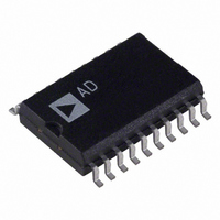
AD73311LAR Analog Devices Inc, AD73311LAR Datasheet - Page 20

AD73311LAR
Manufacturer Part Number
AD73311LAR
Description
IC ANALOG FRONT END 20-SOIC
Manufacturer
Analog Devices Inc
Datasheet
1.AD73311LAR.pdf
(36 pages)
Specifications of AD73311LAR
Rohs Status
RoHS non-compliant
Number Of Bits
16
Number Of Channels
2
Power (watts)
50mW
Voltage - Supply, Analog
3V
Voltage - Supply, Digital
3V
Package / Case
20-SOIC (7.5mm Width)
Single Supply Voltage (min)
2.7V
Single Supply Voltage (max)
3.3V
Package Type
SOIC W
Lead Free Status / RoHS Status
Not Compliant
Available stocks
Company
Part Number
Manufacturer
Quantity
Price
Part Number:
AD73311LAR
Manufacturer:
ADI/亚德诺
Quantity:
20 000
Company:
Part Number:
AD73311LARS
Manufacturer:
AD
Quantity:
12
Part Number:
AD73311LARS
Manufacturer:
ADI/亚德诺
Quantity:
20 000
Company:
Part Number:
AD73311LARS/AD73311
Manufacturer:
LITEON
Quantity:
10 000
Company:
Part Number:
AD73311LARSREEL
Manufacturer:
STM
Quantity:
6 706
Company:
Part Number:
AD73311LARSZ
Manufacturer:
MIC
Quantity:
6 222
Part Number:
AD73311LARSZ
Manufacturer:
ADI/亚德诺
Quantity:
20 000
Part Number:
AD73311LARSZ-REEL
Manufacturer:
ADI/亚德诺
Quantity:
20 000
Part Number:
AD73311LARU
Manufacturer:
ADI/亚德诺
Quantity:
20 000
AD73311L
The AD73311L also features direct sampling at the lower rate
of 8 kHz. This is achieved by the use of extended decimation
registers within the decimator block, which allows for the increased
word growth associated with the higher effective oversampling
ratio. Figure 17 details the spectrum of a 1 kHz test tone converted
at an 8 kHz rate.
The device features an on-chip master clock divider circuit that
allows the sample rate to be reduced as the sampling rate of the
sigma-delta converter is proportional to the output of the MCLK
Divider (whose default state is divide by 1).
The decimator’s frequency response (Sinc3) gives some pass-
band attenuation (up to F
the Nyquist frequency. If it is required to implement a digital
filter to create a sharper cutoff characteristic, it may be prudent
to use an initial sample rate of greater than twice the Nyquist
rate in order to avoid aliasing due to the smooth roll-off of the
Sinc3 filter response.
In the case of voiceband processing where 4 kHz represents the
Nyquist frequency, if the signal to be measured were externally
bandlimited, an 8 kHz sampling rate would suffice. However, if
it is required to limit the bandwidth using a digital filter, it may
be more appropriate to use an initial sampling rate of 16 kHz
and to process this sample stream with a filtering and decimat-
ing algorithm to achieve a 4 kHz bandlimited signal at an 8 kHz
rate. Figure 18 details the initial 16 kHz sampled tone.
–100
–120
–140
100
150
–20
–40
–60
–80
50
0
0
0
0
1000
500
1000
2000
1500
S
3000
FREQUENCY – Hz
/2) which continues to roll off above
FREQUENCY – Hz
2000
4000
2500
5000
3000
6000
3500
7000
4000
8000
Figure 19 details the spectrum of the final 8 kHz sampled
filtered tone.
Encoder Group Delay
When programmed for high sampling rates, the AD73311L
offers a very low level of group delay, which is given by the
following relationship:
where:
If final filtering is implemented in the DSP, the final filter’s
group delay must be taken into account when calculating overall
group delay.
Decoder Section
The decoder section updates (samples) at the same rate as the
encoder section. This rate is programmable as 64 kHz, 32 kHz,
16 kHz or 8 kHz (from a 16.384 MHz MCLK). The decoder
section represents a reverse of the process that was described in
the encoder section. In the case of the decoder section, signals
are applied in the form of samples at an initial low rate. This
sample rate is then increased to the final digital sigma-delta
modulator rate of DMCLK/8 by interpolating new samples
between the original samples. The interpolating filter also has the
action of canceling images due to the interpolation process using
spectral nulls that exist at integer multiples of the initial sam-
pling rate. Figure 20 shows the spectral response of the decoder
section sampling at 64 kHz. Again, its sigma-delta modulator
shapes the noise so it is reduced in the voice bandwidth dc–4 kHz.
For improved voiceband SNR, the user can implement an initial
anti-imaging filter, preceded by 8 kHz to 64 kHz interpolation,
in the DSP.
Order is the order of the decimator (= 3),
M is the decimation factor (= 32 @ 64 kHz, = 64 @ 32 kHz,
= 128 @ 16 kHz , = 256 @ 8 kHz) and
T
on DMCLK = 16.384 MHz) => Group Delay (Decimator @
64 kHz) = 3 × (32 – 1)/2 × (1/2.048e6) = 22.7 µs
DEC
Group Delay (Decimator) = Order × ((M – 1)/2) × T
–100
–120
–140
–20
–40
–60
–80
is the decimation sample interval (= 1/2.048e6) (based
0
0
500
1000
1500
FREQUENCY Hz
2000
2500
3000
3500
4000
DEC


