ISL12032IVZ Intersil, ISL12032IVZ Datasheet - Page 11
ISL12032IVZ
Manufacturer Part Number
ISL12032IVZ
Description
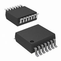
IC RTC LP BATT BACK SRAM 14TSSOP
Manufacturer
Intersil
Type
Clock/Calendar/NVSRAMr
Datasheet
1.ISL12032IVZ-T.pdf
(26 pages)
Specifications of ISL12032IVZ
Memory Size
1K (128 x 8)
Time Format
HH:MM:SS:hh (12/24 hr)
Date Format
YY-MM-DD-dd
Interface
I²C, 2-Wire Serial
Voltage - Supply
2.7 V ~ 5.5 V
Operating Temperature
-40°C ~ 85°C
Mounting Type
Surface Mount
Package / Case
14-TSSOP
Lead Free Status / RoHS Status
Lead free / RoHS Compliant
Available stocks
Company
Part Number
Manufacturer
Quantity
Price
Company:

Part Number:
ISL12032IVZ-T
Manufacturer:
Intersil
Quantity:
11 856


REGISTER ACCESS
The contents of the registers can be modified by performing
a byte or a page write operation directly to any register
address.
The registers are divided into 10 sections. They are:
Write capability is allowable into the RTC registers (00h to
07h) only when the WRTC bit (bit 6 of address 0Ch) is set to
“1”. Other sections do not need to have the WRTC bit set for
write access. A read or write can begin at any address within
the section. A write to sections 2 through 9 can be
continuous. A write can overlap two or more sections as
well.
A register can be read by performing a random read at any
address at any time. This returns the contents of that register
location. Additional registers are read by performing a
sequential read. For the RTC and Alarm registers, the read
instruction latches all clock registers into a buffer, so an
update of the clock does not change the time being read. At
the end of a read, the master supplies a stop condition to
end the operation and free the bus. After a read, the address
remains at the previous address +1 so the user can execute
a current address read and continue reading the next
register.
It is only necessary to set the WRTC bit prior to writing into
the RTC registers. All other registers are completely
accessible without setting the WRTC bit.
1. Real Time Clock (8 bytes): Address 00h to 07h.
2. Status (2 bytes): Address 08h to 09h.
3. Counter (2 bytes): Address Ah to Bh.
4. Control (9 bytes): 0Ch to 14h.
5. Day Light Saving Time (8 bytes): 15h to 1Ch
6. Alarm 0/1 (12 bytes): 1Dh to 28h
7. Time Stamp for Battery Status (5 bytes): Address 29h to
8. Time Stamp for VDD Status (5 bytes): Address 2Eh to
9. Time Stamp for Event Status (5 bytes): 33h to 37h.
2Dh.
32h.
11
ISL12032
April 16, 2009
FN6618.2
Related parts for ISL12032IVZ
Image
Part Number
Description
Manufacturer
Datasheet
Request
R

Part Number:
Description:
Intersil Corporation [CMOS Serial Controller Interface]
Manufacturer:
Intersil Corporation
Datasheet:
Part Number:
Description:
Manufacturer:
Intersil Corporation
Datasheet:
Part Number:
Description:
357-036-542-201 CARDEDGE 36POS DL .156 BLK LOPRO
Manufacturer:
Intersil Corporation
Datasheet:
Part Number:
Description:
1024-Word x 4-Bit LSI Static RAM
Manufacturer:
Intersil Corporation
Datasheet:
Part Number:
Description:
General Purpose NPN Transistor Arrays FN341.4
Manufacturer:
Intersil Corporation
Datasheet:
Part Number:
Description:
CMOS 16-Bit Microprocessor
Manufacturer:
Intersil Corporation
Datasheet:
Part Number:
Description:
Manufacturer:
Intersil Corporation
Datasheet:
Part Number:
Description:
Manufacturer:
Intersil Corporation
Datasheet:
Part Number:
Description:
Manufacturer:
Intersil Corporation
Datasheet:
Part Number:
Description:
Manufacturer:
Intersil Corporation
Datasheet:
Part Number:
Description:
CMOS 6-Bit Latch and Decoder Memory Interfaces
Manufacturer:
Intersil Corporation
Datasheet:
Part Number:
Description:
CA3046General Purpose NPN Transistor Arrays
Manufacturer:
Intersil Corporation
Datasheet:
Part Number:
Description:
Manufacturer:
Intersil Corporation
Datasheet:
Part Number:
Description:
TR909 DLC/FLC SLIC with Low Power Standby
Manufacturer:
Intersil Corporation
Datasheet:
Part Number:
Description:
Manufacturer:
Intersil Corporation
Datasheet: