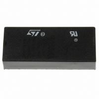
M48T129V-85PM1 STMicroelectronics, M48T129V-85PM1 Datasheet - Page 18

M48T129V-85PM1
Manufacturer Part Number
M48T129V-85PM1
Description
IC TIMEKPR NVRAM 1MBIT 3V 32-DIP
Manufacturer
STMicroelectronics
Series
Timekeeper®r
Type
Clock/Calendar/NVSRAMr
Datasheet
1.M48T129Y-70PM1.pdf
(28 pages)
Specifications of M48T129V-85PM1
Memory Size
1M (128K x 8)
Time Format
HH:MM:SS (24 hr)
Date Format
YY-MM-DD-dd
Interface
Parallel
Voltage - Supply
3 V ~ 3.6 V
Operating Temperature
0°C ~ 70°C
Mounting Type
Through Hole
Package / Case
32-DIP (600 mil) Module
Lead Free Status / RoHS Status
Lead free / RoHS Compliant
Other names
497-2835-5
Available stocks
Company
Part Number
Manufacturer
Quantity
Price
Company:
Part Number:
M48T129V-85PM1
Manufacturer:
ST
Quantity:
450
Company:
Part Number:
M48T129V-85PM1
Manufacturer:
AVAGO
Quantity:
1 137
Clock operations
3.8
3.9
3.10
18/28
Should the watchdog timer time-out, and the WDS bit is programmed to output an interrupt,
a value of “00h” needs to be written to the watchdog register in order to clear the IRQ/FT
pin. This will also disable the watchdog function until it is again programmed correctly. A
READ of the flags register will reset the watchdog flag (bit D7; register 1FFF0h).
The watchdog function is automatically disabled upon power-down and the watchdog
register is cleared. If the watchdog function is set to output to the IRQ/FT pin and the
frequency test function is activated, the watchdog or alarm function prevails and the
frequency test function is denied.
Power-on reset
The M48T129Y/V continuously monitors V
point, the RST pulls low (open drain) and remains low on power-up for t
passes V
to V
Battery low warning
The M48T129Y/V automatically performs battery voltage monitoring upon power-up and at
factory-programmed time intervals of approximately 24 hours. The battery low (BL) bit, bit
D4 of flags register 1FFF0h, will be asserted if the battery voltage is found to be less than
approximately 2.5 V.
If a battery low is generated during a power-up sequence, this indicates that the battery is
below approximately 2.5 volts and may not be able to maintain data integrity in the SRAM.
Data should be considered suspect and verified as correct.
If a battery low indication is generated during the 24-hour interval check, this indicates that
the battery is near end of life. However, data is not compromised due to the fact that a
nominal V
The M48T129Y/V only monitors the battery when a nominal V
Thus applications which require extensive durations in the battery back-up mode should be
powered-up periodically (at least once every few months) in order for this technique to be
beneficial. Additionally, if a battery low is indicated, data integrity should be verified upon
power-up via a checksum or other technique.
Initial power-on defaults
Upon application of power to the device, the following register bits are set to a '0' state:
WDS, BMB0-BMB4, RB0,RB1, AFE, ABE, W, R and FT.
CC
should be chosen to control the rise time.
PFD
CC
is supplied.
(max). The RST pin is an open drain output and an appropriate pull-up resistor
Doc ID 5710 Rev 4
CC
. When V
CC
falls to the power fail detect trip
CC
is applied to the device.
M48T129V, M48T129Y
REC
after V
CC


