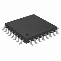
MAX3676EHJ Maxim Integrated Products, MAX3676EHJ Datasheet - Page 13

MAX3676EHJ
Manufacturer Part Number
MAX3676EHJ
Description
IC RECOV/RETIME 622MBPS 32-TQFP
Manufacturer
Maxim Integrated Products
Type
Clock and Data Recovery (CDR)r
Datasheet
1.MAX3676EHJ.pdf
(15 pages)
Specifications of MAX3676EHJ
Input
PECL
Output
PECL
Frequency - Max
622MHz
Voltage - Supply
3 V ~ 5.5 V
Operating Temperature
-40°C ~ 85°C
Mounting Type
Surface Mount
Package / Case
32-TQFP, 32-VQFP
Frequency-max
622MHz
Lead Free Status / RoHS Status
Contains lead / RoHS non-compliant
Available stocks
Company
Part Number
Manufacturer
Quantity
Price
Part Number:
MAX3676EHJ
Manufacturer:
MAXIM/美信
Quantity:
20 000
Company:
Part Number:
MAX3676EHJ+
Manufacturer:
MAXIM
Quantity:
67
Company:
Part Number:
MAX3676EHJ+
Manufacturer:
Maxim Integrated
Quantity:
10 000
Company:
Part Number:
MAX3676EHJ+T
Manufacturer:
Maxim Integrated
Quantity:
10 000
Part Number:
MAX3676EHJ+T
Manufacturer:
MAXIM/美信
Quantity:
20 000
Company:
Part Number:
MAX3676EHJ-T
Manufacturer:
Maxim Integrated
Quantity:
10 000
allowable pattern-dependent jitter, peak-to-peak
(seconds); and BW = typical system bandwidth, nor-
mally 0.6 to 1.0 times the data rate (Hertz). If the PDJ is
still larger than desired, continue increasing the value of
C
MAX3676 analog inputs (ADI+, ADI-), it is important to
keep the low-frequency cutoff associated with C
below the corner frequency associated with C
(Table 1).
PDJ can also be present due to insufficient high-fre-
quency bandwidth (Figure 10). If the amplifiers are not
fast enough to allow for complete transitions during sin-
gle-bit patterns, or if the amplifier does not allow ade-
quate settling time, high-frequency PDJ can result.
Finally, PWD occurs when the midpoint crossing of a
0–1 transition and a 1–0 transition does not occur at the
Figure 10. Pattern-Dependent Jitter Due to High-Frequency
Rolloff
IN
. Note that to maintain stability when using the
LONG
CONSECUTIVE
BIT STREAM
0-1-0 BIT STREAM
Data-Retiming IC with Limiting Amplifier
______________________________________________________________________________________
HF PDJ
Pulse-Width Distortion
622Mbps, 3.3V Clock-Recovery and
TIME
MIDPOINT
IN
OLC
(f
C
)
same level (Figure 11). DC offsets and nonsymmetrical
rising and falling edge speeds both contribute to PWD.
For a 1–0 bit stream, calculate PWD as follows:
The internal clock and data alignment in the MAX3676
is well maintained close to the center of the data eye.
Although not required, this sampling point can be shift-
ed using the PHADJ inputs to optimize BER perfor-
mance. The PHADJ inputs operate with differential
input signals to approximately ±1V. A simple resistor
divider with a bypass capacitor is sufficient to set up
these levels. When the PHADJ inputs are not used, they
should be tied directly to V
Figure 11. Pulse-Width Distortion
PWD = [(width of wider pulse) -
(width of narrower pulse)]/2
PWD RESULTS WHEN THE WIDTH
OF A ZERO DOES NOT EQUAL
THE WIDTH OF A ONE.
WIDTH OF A ZERO
WIDTH OF A ONE
CC
t
FALL
.
≠ t
RISE
Phase Adjust
MIDPOINT
TIME
13


