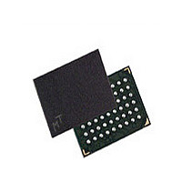
MT45W2MW16BGB-701 IT Micron Technology Inc, MT45W2MW16BGB-701 IT Datasheet - Page 34

MT45W2MW16BGB-701 IT
Manufacturer Part Number
MT45W2MW16BGB-701 IT
Description
Manufacturer
Micron Technology Inc
Datasheet
1.MT45W2MW16BGB-701_IT.pdf
(61 pages)
Specifications of MT45W2MW16BGB-701 IT
Operating Temperature (max)
85C
Operating Temperature (min)
-40C
Mounting
Surface Mount
Operating Temperature Classification
Industrial
Lead Free Status / RoHS Status
Compliant
- Current page: 34 of 61
- Download datasheet (2Mb)
Maximum and Typical Standby Currents
Table 9:
Figure 25:
PDF: 09005aef82832fa2/Source: 09005aef82832f5f
32mb_burst_cr1_0_p24z_2.fm - Rev. E 9/08 EN
Description
Partial-array refresh
standby current
Partial-Array Refresh Specifications and Conditions
Typical Refresh Current vs. Temperature
70
60
50
40
30
20
10
0
–45
–35
Note:
–25
The following table and figure refer to the maximum and typical standby currents for the
MT45W2MW16BGB device. The typical values shown in Figure 25 are measured with
the default on-chip temperature sensor control enabled.
V
IN
Conditions
CE# = V
I
changes to the PAR array partition or when entering standby mode. To achieve low
standby current, all inputs must be driven either to V
–15
= V
PAR
CC
(MAX) values measured at 85°C. I
32Mb: 2 Meg x 16 Async/Page/Burst CellularRAM 1.0 Memory
–05
Q or 0V;
CC
Q
Temperature (°C)
05
15
I
PAR
25
Symbol
35
34
(no designation)
Standard power
45
Micron Technology, Inc., reserves the right to change products or specifications without notice.
PAR
55
might be slightly higher for up to 500ms after
65
Array Partition
75
CC
Full
1/2
1/4
1/8
85
0
Q or V
Electrical Characteristics
95
SS
©2007 Micron Technology, Inc. All rights reserved.
.
Max
PAR full
PAR 1/2
PAR 1/4
PAR 0
110
105
95
95
70
Unit
µA
Related parts for MT45W2MW16BGB-701 IT
Image
Part Number
Description
Manufacturer
Datasheet
Request
R

Part Number:
Description:
IC SDRAM 64MBIT 133MHZ 54TSOP
Manufacturer:
Micron Technology Inc
Datasheet:

Part Number:
Description:
IC SDRAM 64MBIT 5.5NS 86TSOP
Manufacturer:
Micron Technology Inc
Datasheet:

Part Number:
Description:
IC SDRAM 64MBIT 200MHZ 86TSOP
Manufacturer:
Micron Technology Inc
Datasheet:

Part Number:
Description:
IC SDRAM 64MBIT 133MHZ 54TSOP
Manufacturer:
Micron Technology Inc
Datasheet:

Part Number:
Description:
IC SDRAM 128MBIT 133MHZ 54TSOP
Manufacturer:
Micron Technology Inc
Datasheet:

Part Number:
Description:
IC SDRAM 256MBIT 133MHZ 90VFBGA
Manufacturer:
Micron Technology Inc
Datasheet:

Part Number:
Description:
IC SDRAM 128MBIT 133MHZ 54TSOP
Manufacturer:
Micron Technology Inc
Datasheet:

Part Number:
Description:
IC SDRAM 256MBIT 133MHZ 54TSOP
Manufacturer:
Micron Technology Inc
Datasheet:

Part Number:
Description:
IC DDR SDRAM 512MBIT 6NS 66TSOP
Manufacturer:
Micron Technology Inc
Datasheet:

Part Number:
Description:
IC SDRAM 128MBIT 167MHZ 86TSOP
Manufacturer:
Micron Technology Inc
Datasheet:

Part Number:
Description:
IC SDRAM 128MBIT 143MHZ 86TSOP
Manufacturer:
Micron Technology Inc
Datasheet:

Part Number:
Description:
SDRAM 256M-BIT 1.8V 54-PIN VFBGA
Manufacturer:
Micron Technology Inc
Datasheet:

Part Number:
Description:
IC SDRAM 128MBIT 143MHZ 86TSOP
Manufacturer:
Micron Technology Inc
Datasheet:

Part Number:
Description:
IC SDRAM 128MBIT 125MHZ 54VFBGA
Manufacturer:
Micron Technology Inc
Datasheet:

Part Number:
Description:
IC SDRAM 128MBIT 125MHZ 54VFBGA
Manufacturer:
Micron Technology Inc
Datasheet:


