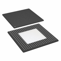
AD8152JBP Analog Devices Inc, AD8152JBP Datasheet - Page 24

AD8152JBP
Manufacturer Part Number
AD8152JBP
Description
Digital Crosspoint 34 x 34 X-Point SW 3.2Gbps 256-Pin SBGA
Manufacturer
Analog Devices Inc
Datasheet
1.AD8152JBPZ.pdf
(32 pages)
Specifications of AD8152JBP
Package
256SBGA
Array Configuration
34x34
Number Of Arrays
1
Maximum Data Rate
3.2 Gbps
Power Supply Type
Single
Minimum Single Supply Voltage
2.25 V
Maximum Single Supply Voltage
3.63 V
Rohs Status
RoHS non-compliant
Function
Crosspoint Switch
Circuit
1 x 34:34
Voltage Supply Source
Single Supply
Voltage - Supply, Single/dual (±)
2.5 V ~ 3.3 V
Current - Supply
32mA
Operating Temperature
0°C ~ 85°C
Mounting Type
Surface Mount
Package / Case
256-BGA Exposed Pad, 256-eBGA, 256-HBGA
Lead Free Status / RoHS Status
Available stocks
Company
Part Number
Manufacturer
Quantity
Price
Company:
Part Number:
AD8152JBP
Manufacturer:
ADI
Quantity:
170
Company:
Part Number:
AD8152JBP
Manufacturer:
Analog Devices Inc
Quantity:
10 000
Company:
Part Number:
AD8152JBPZ
Manufacturer:
ADI
Quantity:
642
Company:
Part Number:
AD8152JBPZ
Manufacturer:
Analog Devices Inc
Quantity:
10 000
AD8152
EVALUATION BOARD CONTROL SOFTWARE
The AD8152 evaluation board can be controlled by using a PC
and a custom software program. The hardware interface uses a
PC parallel (or printer) port. A standard printer cable is used to
connect from the PC DB-25 connector to the Centronics-type
connector on the evaluation board. Figure 17 shows an evaluation
board control panel from a PC display.
A single screen allows control of all the programmable functions
of the AD8152. The programming modes are listed in the Mode
box. Select either I/O Programming or Current Programming by
selecting the appropriate radio button. These will allow either
programming the switch matrix or the output currents one at a time.
An alternative is to use the Broadcast mode. This will either
simultaneously program all of the outputs to one selected input
or program all outputs to the same current.
In the I/O Programming mode (nonbroadcast), the desired input
is selected from the Input Select box by double-clicking on the
appropriate input channel number. This will cause the same
channel to appear in the Active Input Selection indicator window.
Figure 17. Evaluation Board Control Panel
–24–
Next, select the desired output from the Output Select box by double-
clicking the appropriate output channel number.
Finally, the Program button is clicked and the data is immediately
sent to the evaluation board for programming the part to the
selected I/O combination.
If an additional output(s) is desired to be programmed to the same
input, double-click the desired output channel number and click
the Program button.
The Programmed Output table indicates which outputs are
programmed to the input that is indicated in the Active Input
Selection window. If it is desired to disable an individual output,
its radio button in the Programmed Output table can be clicked,
and it will change from black to white to indicate that it is not
enabled. Note: It is not possible to program outputs by selecting
their radio buttons.
To observe the set of outputs that are connected to any input,
double-click the desired input channel number from the Input
Select box. The selected channel number will show up in the Active
Input Selection window and the programmed outputs will have a
black dot in their radio button in the Programmed Output table.
To program an output current, select the Current Programming
button in the Mode box. Then double-click the desired output
channel number from the Output Select table. Next double-click
the desired entry for the Output Current. Finally, click the
Program button.
If the Broadcast button is selected from the Mode box, all outputs
will be treated the same. If I/O Programming is selected, double-
click the input channel number from the Input Select table
and click the Program button. This will cause all outputs to be
programmed to the selected output, and all of the buttons will
have a black dot in the Programmed Output table.
For broadcast current programming, double-click the desired
Output Current. Then click the Program button. All of the outputs
will be programmed to the selected output current.
The Reset button will disable all outputs. In addition, all output
currents will be programmed to the nominal value of 16 mA.
REV. A


