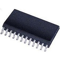
CS5461A-ISZR Cirrus Logic Inc, CS5461A-ISZR Datasheet - Page 27

CS5461A-ISZR
Manufacturer Part Number
CS5461A-ISZR
Description
IC Sngl-Phs Bi-Directional Power/Energy
Manufacturer
Cirrus Logic Inc
Datasheet
1.CS5461A-ISZ.pdf
(44 pages)
Specifications of CS5461A-ISZR
Input Impedance
30 KOhm
Measurement Error
0.1%
Voltage - I/o High
0.8V
Voltage - I/o Low
0.2V
Current - Supply
2.9mA
Voltage - Supply
4.75 V ~ 5.25 V
Operating Temperature
-40°C ~ 85°C
Mounting Type
Surface Mount
Package / Case
24-SSOP
Meter Type
Single Phase
Lead Free Status / RoHS Status
Lead free / RoHS Compliant
For Use With
598-1552 - BOARD EVAL & SOFTWARE CS5461A
Lead Free Status / Rohs Status
Lead free / RoHS Compliant
Available stocks
Company
Part Number
Manufacturer
Quantity
Price
Part Number:
CS5461A-ISZR
Manufacturer:
CIRRUS
Quantity:
20 000
6.2 Current and Voltage DC Offset Register ( I
6.3 Current and Voltage Gain Register ( I
6.4 Cycle Count Register
DS661F2
MSB
MSB
MSB
-(2
2
2
23
1
Address: 1 (Current DC Offset); 3 (Voltage DC Offset)
0
Default = 0x000000
The DC Offset registers (I
register is updated with the DC offset measured over a computation cycle. DRDY will be asserted at the end of
the calibration. This register may be read and stored for future system offset compensation. The value is repre-
sented in two's complement notation and in the range of -1.0 ≤ I
right of the MSB.
Address: 2 (Current Gain); 4 (Voltage Gain)
Default = 0x400000 = 1.000
The gain registers (I
the register is updated with the gain measured over a computation cycle. DRDY will be asserted at the end of
the calibration. This register may be read and stored for future system gain compensation. The value is in the
range 0.0 ≤ I
iCPU
K[3:0]
Address: 5
Default = 0x000FA0 = 4000
Cycle Count, denoted as N, determines the length of one computation cycle. During continuous conversions,
the computation cycle frequency is (MCLK/K)/(1024∗N). A one second computational cycle period occurs when
MCLK = 4.096 MHz, K = 1, and N = 4000.
)
2
2
2
22
-1
0
2
2
2
gn
21
-2
-1
,V
are sampled, the logic driven by CPUCLK should not be active during the sample edge.
0 = Normal operation (default)
1 = Minimize noise when CPUCLK is driving rising-edge logic
clock DCLK. The internal clock frequency is DCLK = MCLK/K. The value of K can range be-
tween 1 and 16. A value of “0000” will set K to 16 (not zero). K = 1 at reset.
Inverts the CPUCLK clock. In order to reduce the level of noise present when analog signals
Clock divider. A 4-bit binary number used to divide the value of MCLK to generate the internal
gn
< 3.9999, with the binary point to the right of the second MSB.
2
2
2
gn
20
-3
-2
,V
gn
DCoff
)
2
2
2
are initialized to 1.0 on reset. When either a AC or DC Gain calibration is performed,
19
-4
-3
,V
DCoff
2
2
2
18
-5
-4
)
are initialized to 0.0 on reset. When DC Offset calibration is performed, the
2
2
2
17
-6
-5
gn
,V
2
2
2
16
-7
-6
gn
DCoff
)
.....
.....
.....
,V
DCoff
2
2
2
-17
-16
DCoff
6
)
, V
2
2
2
-18
-17
DCoff
5
< 1.0, with the binary point to the
2
2
2
-19
-18
4
2
2
2
-20
-19
3
2
2
2
-21
-20
2
CS5461A
2
2
2
-22
-21
1
LSB
LSB
LSB
2
2
2
-23
-22
0
27


